Supercharge Your Innovation With Domain-Expert AI Agents!

Dynamic alignment of optical fibers to optical circuit devices such as planar lightwave circuits

a technology of optical circuit devices and optical fibers, applied in the direction of optical elements, measurement devices, instruments, etc., can solve the problems of inherently complex nature of the operation, affecting the overall device performance, and time-consuming

Inactive Publication Date: 2005-08-30
GEMFIRE CORP
View PDF13 Cites 3 Cited by
  • Summary
  • Abstract
  • Description
  • Claims
  • Application Information

AI Technical Summary

Benefits of technology

[0007]An improved method of aligning an optical fiber or optical fiber array to an optical circuit device couples an optical signal source and an optical measuring device to the optical fiber array, the other side of which array is coupled to the same side of the optical circuit device, thereby forming an initial optical path from the optical signal source to the optical fiber array to the optical circuit device to the optical fiber array and to the optical measuring device. The optical path is adjusted until the optical measuring device finds a characteristic of the optical signal to be satisfactory. At that time, the final alignment may be fixed or made permanent. The characteristic of the optical signal may include, for example, the intensity or insertion loss of the optical signal.

Problems solved by technology

The accuracy with which this process is executed can affect the overall device performance.
The complexity of this scheme is significant in that each unit must have its own independent positioning system.
The nature of this operation is inherently complex and time consuming.
The displacement may include warping and twisting that will affect the planarity of the finished assembly.
The approach is mechanically complex because it requires a six degree-of-freedom positioning mechanism for each of the three independent units.
Further, the time required for the alignment process to converge to the optimal alignment is long and extended due to an unconstrained geometry and an inherently iterative, sequential process.
Also, the optimal alignment for the assembly, which comprises a series of optical paths, is no better than the insertion loss of the optically worst path of the series of paths.
Another issue is the accumulation of mechanical tolerances.
By cascading all of the alignment parameters into a single operation, it is not possible to optimize sub-alignment tasks.

Method used


Image

  • Dynamic alignment of optical fibers to optical circuit devices such as planar lightwave circuits
  • Dynamic alignment of optical fibers to optical circuit devices such as planar lightwave circuits
  • Dynamic alignment of optical fibers to optical circuit devices such as planar lightwave circuits

Examples


Embodiment Construction

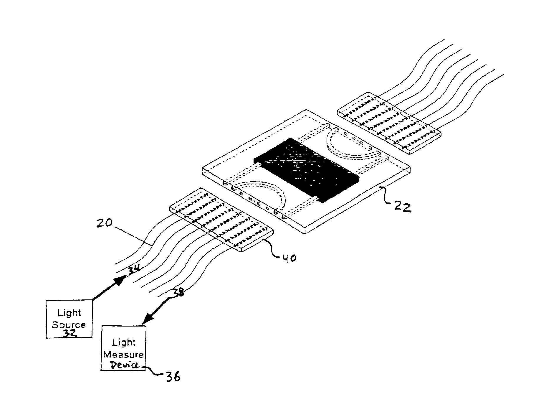
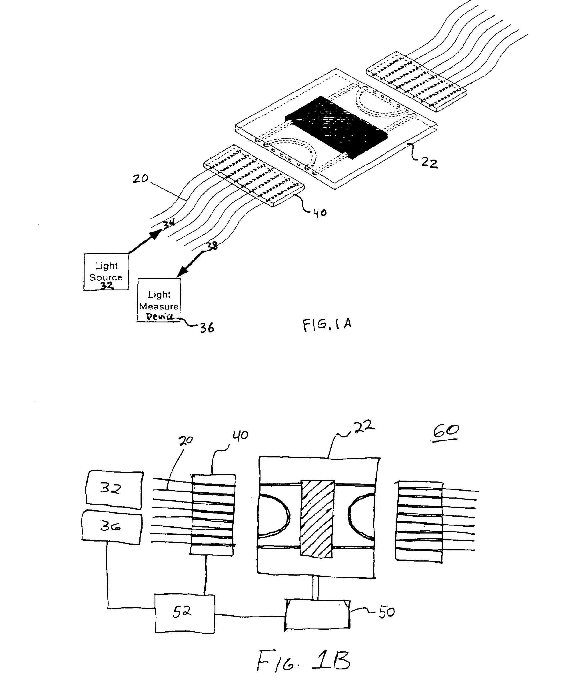
[0013]FIG. 1A is a block diagram representation of an example embodiment of an optical alignment system for aligning an optical fiber or optical fiber array20 to an optical circuit device 22 such as a PLC. The optical fiber or optical fiber array 20 may also be referred to as an optical waveguide(s) or optical element. Preferably, the optical circuit device 22 is a PLC. For convenience, the optical circuit device 22 may be referred to as a PLC 22 even though other types of optical circuit devices, such as one containing a light-guiding element in an optical fiber array, are also contemplated. The optical alignment system uses a loopback feature to provide an optical circuit path that allows an active optical alignment of the optical fiber array 20 to the PLC 22 to occur independent of the state of the PLC 22. The optical alignment system preferably is a “U”-shaped optically conductive path whose endpoints 34, 38 reside on the same side of the PLC 22. An optical signal source 32 is a...


PUM


Abstract

An improved method and system of aligning an optical fiber or optical fiber array to an optical circuit device couples an optical signal source and an optical measuring device to the optical fiber array, the other side of which array is coupled to the same side of the optical circuit device, thereby forming an initial U-shaped optical path from the optical signal source to the optical fiber array to the optical circuit device to the optical fiber array and to the optical measuring device. The optical path is adjusted until the optical measuring device finds a characteristic of the optical signal to be satisfactory. At that time, the final alignment may be fixed or made permanent. The characteristic of the optical signal may include, for example, the intensity of the optical signal, which is preferably at a maximum or the insertion loss which is preferably at a minimum.

Description

FIELD OF THE INVENTION[0001]The field of the invention relates generally to the alignment of optical devices and more particularly, to the alignment of optical fibers and / or optical fiber arrays to optoelectronic devices in the form of planar lightwave circuits (“PLC”).BACKGROUND[0002]Optical fibers and / or optical fiber arrays may be connected to optoelectronic devices in the form of planar lightwave circuits (PLC). The alignment of such connections is important as it affects the quality of the transmitted optical signal (e.g., its intensity and / or insertion loss). Attaching optical fibers to PLC devices is a fundamental aspect of the manufacturing and assembly process. The accuracy with which this process is executed can affect the overall device performance. Present alignment methodologies for a multi-ported optical device require the simultaneous positioning, or alignment, of at least three independent physical units, in free space. The complexity of this scheme is significant in...

Claims


Application Information

Patent Timeline
Patent Type & Authority Patents(United States)
IPC IPC(8): G02B6/42
CPCG02B6/4222G02B6/4225G02B6/4227
Inventor MUKAI, PAUL VICTOR
Owner GEMFIRE CORP
Features
  • R&D
  • Intellectual Property
  • Life Sciences
  • Materials
  • Tech Scout
  • Unparalleled Data Quality
  • Higher Quality Content
  • 60% Fewer Hallucinations
Learn More