Source synchronous receiver link initialization and input floating control by clock detection and DLL lock detection

a clock detection and source synchronous receiver technology, applied in multiplex communication, generating/distributing signals, instruments, etc., can solve the problems of power being cut off from the clock signal buffer, and power being los

Inactive Publication Date: 2005-08-30
ORACLE INT CORP
View PDF11 Cites 38 Cited by
  • Summary
  • Abstract
  • Description
  • Claims
  • Application Information

AI Technical Summary

Benefits of technology

[0012]Thus, in various embodiments, the source synchronous receiver may solve some of the problems associated with source synchronous I/O. The ability to perform a local reset ma...

Problems solved by technology

Upon failure of the clock verification circuit to receive the clock detect circuit, the receiver enable signal may be de-asserted, thereby causing power to be cut off from the clock signal buffe...

Method used


Image

  • Source synchronous receiver link initialization and input floating control by clock detection and DLL lock detection
  • Source synchronous receiver link initialization and input floating control by clock detection and DLL lock detection
  • Source synchronous receiver link initialization and input floating control by clock detection and DLL lock detection

Examples


Embodiment Construction

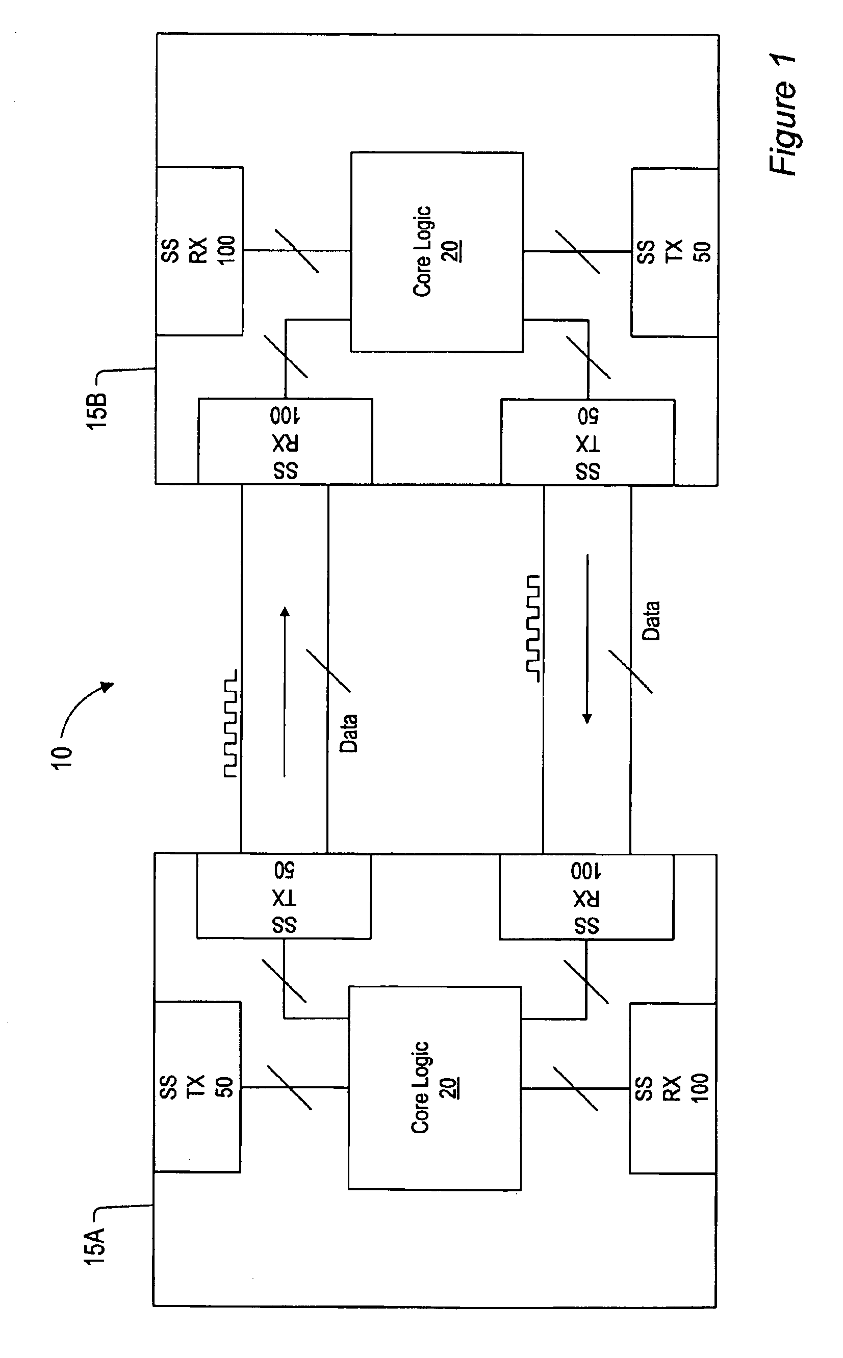
[0019]Moving now to FIG. 1, a block diagram illustrating one embodiment of a system utilizing source synchronous I / O is shown. System 10 is an exemplary system which includes two integrated circuits (ICs) 15A and 15B that are configured for source synchronous I / O operations. Each IC includes a plurality of source synchronous transmitters (SST's) 50 and source synchronous receivers (SSR's) 100. Each SST 50 and SSR 100 is coupled to core logic 20 of its respective IC.

[0020]IC's 15A and 15B may be any type of integrated circuit that may be configured for source synchronous communications. Examples of such IC's include processors, application specific integrated circuits (ASICs), peripheral chips, and so on. The primary functions of each of IC 15A and IC 15B may be performed by its core logic 20. IC's 15A and 15B may be implemented on a system board (i.e. motherboard) of a computer system. IC's 15A and 15B may also be implemented on various daughter cards or in peripheral devices. It sh...


PUM


Abstract

A method and apparatus for operating a source synchronous receiver. In one embodiment, a source synchronous receiver may include a clock receiver comprising a clock detector and a clock signal buffer. The clock detector may be configured to detect a first clock signal and assert a clock detect signal responsive to detecting the first clock signal. The clock buffer may receive the first clock signal and produce a second clock signal, which may be driven to a digital locked loop (DLL) circuit, where the second clock signal is regenerated and driven to a data buffer of the source synchronous receiver. The clock detect signal may be received by a clock verification circuit. The clock verification circuit may be configured to initiate a reset of the source synchronous receiver upon a failure to receive the clock detect signal. The resetting of the source synchronous receiver may be performed locally, and does not reset the core logic of the device in which it is implemented, nor any other source synchronous port on the device. Thus, other source synchronous ports on the device, as well as the core logic, may be able to continue operations as normal. The method and apparatus may include a source synchronous receiver that is hot-swappable.

Description

BACKGROUND OF THE INVENTION[0001]1. Field of the Invention[0002]This invention relates to electronic circuits, and more particularly, clock circuits for providing timing signals.[0003]2. Description of the Related Art[0004]As the operating speed of computer processors has increased, the operating speeds of system boards implementing these processors has increased as well in order to eliminate or reduce the effects of bottlenecks. With the clock speeds of processors approaching 1 GHz it is not uncommon for system boards to operate at a clock speed exceeding 100 MHz.[0005]Source synchronous I / O may eliminate or minimize problems that may occur when the data transfers a synchronized to a single system clock. Source synchronous I / O may allow more flexibility in designing system boards, as the clock speed used by source synchronous I / O lines may scale with the processor clock speeds. Furthermore, the use of source synchronous I / O may eliminate length constraints on signal lines.[0006]In ...

Claims


Application Information

Patent Timeline
IPC IPC(8): H03L7/08H03L7/081H03L7/095H04L7/00G06F1/12
CPCH03L7/0812H03L7/095H04L7/0008H04L7/00
Inventor FONG, WAIJONG, JYH-MINGYUAN, LEOSMITH, BRIANCHAKRABARTI, PRABHANSU
Owner ORACLE INT CORP
Why Eureka
Try Eureka