Integrated RF signal level detector usable for automatic power level control

a technology of automatic power level control and detector, applied in power management, instruments, transmission monitoring, etc., can solve the problems of limiting the degree of integration with which a corresponding transceiver device may be manufactured, inherently higher power consumption of amplifiers operating at higher frequencies, and reducing the degree of integration. , to achieve the effect of minimizing variations and improving stability

Inactive Publication Date: 2005-08-30
GLOBALFOUNDRIES INC
View PDF18 Cites 21 Cited by
  • Summary
  • Abstract
  • Description
  • Claims
  • Application Information

AI Technical Summary

Benefits of technology

[0010]Generally, the present invention is directed at an RF signal level analyzing circuit that is advantageously usable in output power control of transceiver devices, wherein an improved stability is achieved in that one or more DC reference voltages are converted int

Problems solved by technology

A key issue in this respect is the degree of integration with which a corresponding transceiver device may be manufactured.
Although the super-heterodyne architecture is well-established and allows the fabrication of reliably operating devices, the highly selective RF filters necessary for the proper operation of these devices require the employment of capacitors and inductors of high quality, thereby restricting the degree of integration achievable, since high quality inductors may not be easily implemented into a semiconductor substrate.
This fact and an inherently higher power consumption of amplifiers operating at higher frequencies caused the reintroduction of the very old so-called direct conversion technique, in which the small signal band, also referred to as base band, is directly up-converted into the RF frequency band during transmission and is directly down-converted to the base band upon receiving the RF carrier signal.
One issue in this respect is the control of the signal level output by the trans

Method used


Image

  • Integrated RF signal level detector usable for automatic power level control
  • Integrated RF signal level detector usable for automatic power level control
  • Integrated RF signal level detector usable for automatic power level control

Examples


Embodiment Construction

[0023]While the present invention is described with reference to the embodiments as illustrated in the following detailed description as well as in the drawings, it should be understood that the following detailed description as well as the drawings are not intended to limit the present invention to the particular illustrative embodiments disclosed, but rather the described illustrative embodiments merely exemplify the various aspects of the present invention, the scope of which is defined by the appended claims.

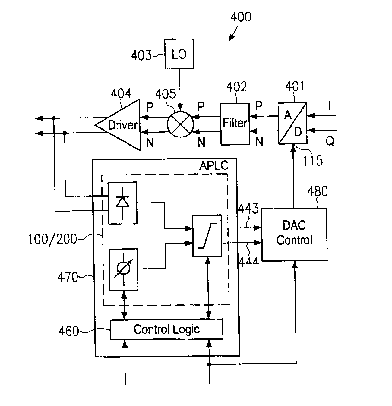
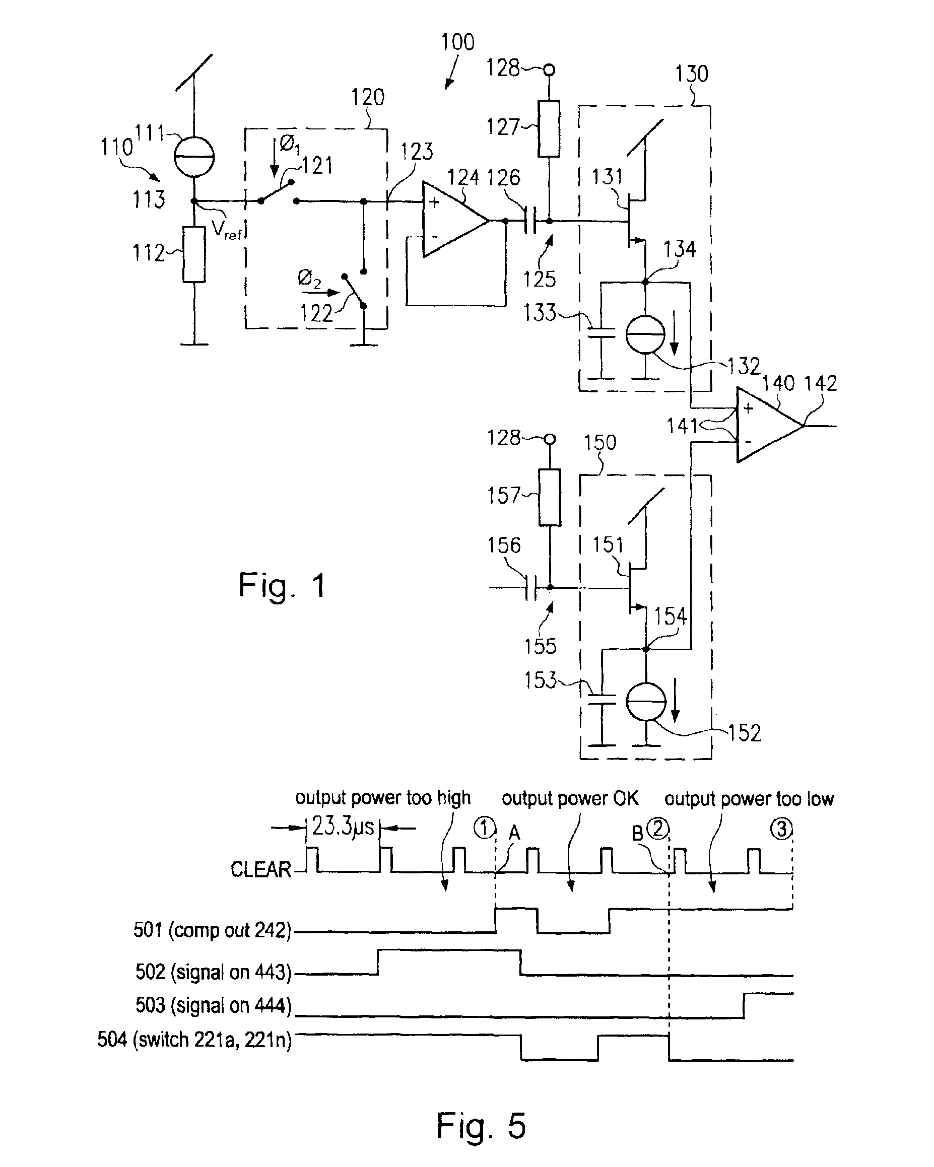
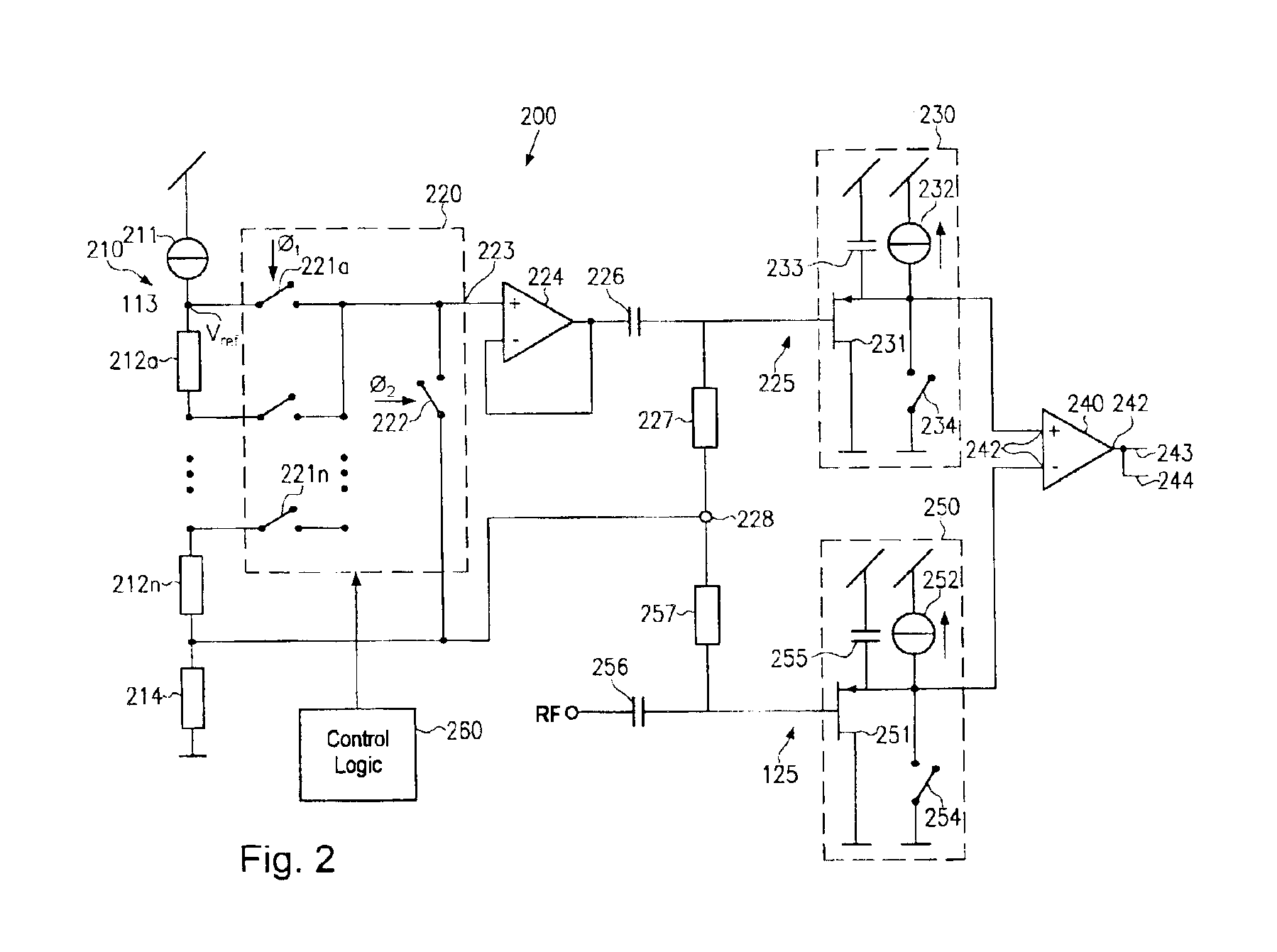
[0024]FIG. 1 shows a circuit diagram referring to a first illustrative embodiment of an RF signal level analyzing circuit 100, in which an RF signal level is compared to an AC reference voltage. The circuit 100 comprises a DC reference voltage source 110 configured to generate a DC reference voltage Vref. In the illustrative embodiment of FIG. 1, the reference voltage source 110 may comprise a constant current source 111 and a resistor 112 connected in series, wherein the re...


PUM


Abstract

A radio frequency signal level is determined by generating an AC reference voltage from a DC reference voltage and determining an envelope of the AC reference voltage in an envelope detector having substantially the same composition as an envelope detector for determining the envelope of the radio frequency signal. The AC reference voltage substantially eliminates any DC offset and thus induces a high immunity against temperature and power supply variations. Moreover, using substantially the same RF signal path for the RF signal and the reference signal, signal distortions cause by the RF signal path are substantially compensated for.

Description

FIELD OF THE PRESENT INVENTION[0001]The present invention generally relates to automated methods for determining a radio frequency (RF) signal emitted by a transmitter device, such as used in wireless communication systems including, for example, wireless local area networks (WLAN), mobile ‘phones, and the like, and more particularly relates to an on-chip detection system for RF signals that may readily be implemented into an integrated automatic power level control system.DESCRIPTION OF THE PRIOR ART[0002]Due to the ever increasing demand for two-way wireless communication systems currently great efforts are being made to develop transmitter / receiver devices, and the following referred to as transceiver, offering a high degree of reliability at low cost. A key issue in this respect is the degree of integration with which a corresponding transceiver device may be manufactured. Additionally, in many applications such as mobile ‘phones, mobile computer applications, and the like, low ...

Claims


Application Information

Patent Timeline
IPC IPC(8): H03G3/30H04B7/005
CPCH03G3/3036H04W52/52H03G3/3052
Inventor EHRENREICH, SEBASTIANDATHE, LUTZSANDIG, KARL-HEINZ
Owner GLOBALFOUNDRIES INC
Why Eureka
Try Eureka