Electric parking brake mechanism

a technology of brake mechanism and electric motor, which is applied in the direction of brake system, gearing, transportation and packaging, etc., can solve the problems of increasing the number of parts, difficult to downsize a total apparatus, poor mechanical efficiency, etc., and achieve the effect of preventing the deterioration of mechanical efficiency

Inactive Publication Date: 2005-09-06
AKEBONO BRAKE IND CO LTD
View PDF6 Cites 22 Cited by
  • Summary
  • Abstract
  • Description
  • Claims
  • Application Information

AI Technical Summary

Benefits of technology

[0007]Therefore, it is an object of the invention to resolve the above-described problem by providing an electric parking brake mechanism capable of holding and releasing a parking brake by a braking force generating motor and capable of preventing a mechanical efficiency from being deteriorated without needing an actuator exclusive for the parking brake.

Problems solved by technology

However, according to the constitution described in JP-A-04-108058, a reduction gear of a worm gear type is used as the irreversible mechanism and therefore, mechanical efficiency is poor, the electric motor needs to be large-sized in order to sufficiently increase pressing force and it is difficult to downsize a total of the apparatus.
Further, according to a constitution described in JP-T-2000-514540, the actuator (electromagnet) exclusive for the parking brake is needed for operating the parking brake and there poses a problem that a number of parts is increased and downsizing of the apparatus is difficult and so on.

Method used


Image

  • Electric parking brake mechanism
  • Electric parking brake mechanism
  • Electric parking brake mechanism

Examples


Embodiment Construction

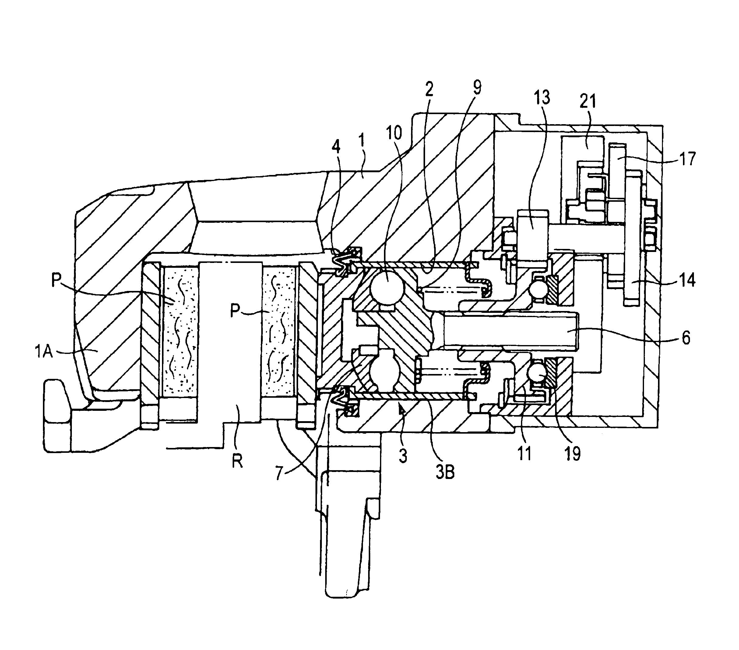
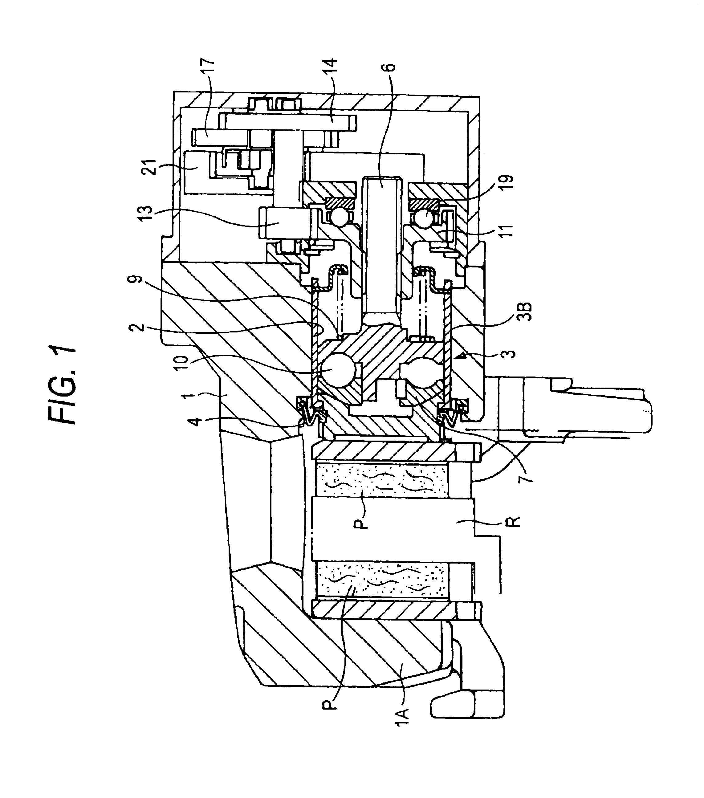
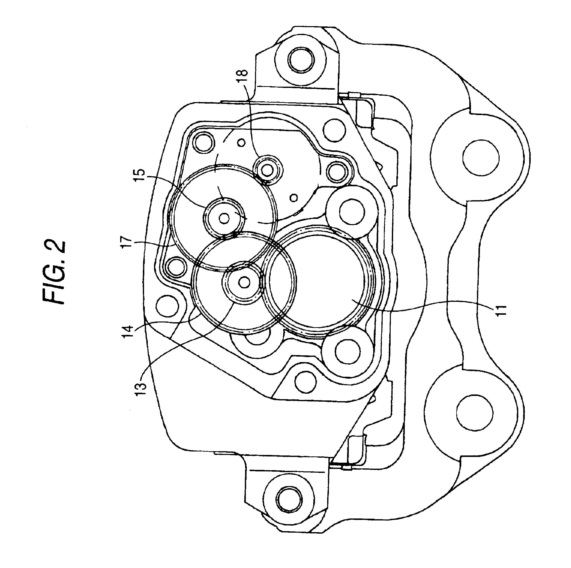
[0022]Explaining an embodiment of the invention in reference to the drawing as follows, FIG. 1 is a side sectional view of an electric brake according to the embodiment, FIG. 2 is a front view of a speed reducing mechanism, FIG. 3 is a plane view of the electric brake, FIG. 4 is an enlarged view of a piston and a force transmission converting mechanism, FIG. 5 is a constitution view of an electric parking brake mechanism, FIG. 6 illustrates a sectional view and a front view of a constituent part of the electric parking brake mechanism, FIG. 7 is a state view of the electric parking brake mechanism in operating a brake, FIG. 8 is a state view of the electric parking brake mechanism in releasing the brake, and FIG. 9 is a state view of the electric parking brake mechanism in operating a parking brake.

[0023]In FIG. 1, as is publicly known, an electric brake apparatus is constructed by a constitution having a caliper 1, provided with a brake pad P as a friction member opposed to a brake...


PUM


Abstract

An electric parking brake mechanism characterized in an electric parking brake for pressing a friction member to a braked member via a force transmission converting mechanism for converting a rotational movement of an electric motor to a linear movement, including an input shaft connected to a side of the electric motor, an output shaft connected to a side of a brake mechanism for pressing the friction member to the brake member and a cam mechanism interposed between the input shaft and the output shaft, the cam mechanism is provided with a plurality of cam members and each having a cam face having a radius gradually increasing relative to a rotational center and in driving only a side of the output shaft, rotation of the output shaft is hampered by operating all of the plurality of cam members to constitute sides of large diameters.

Description

BACKGROUND OF THE INVENTION[0001]The present invention relates to an electric parking brake mechanism capable of being integrated to an electric brake, particularly relates to an electric parking brake mechanism using an electric motor in an electric brake as a drive source and dispensing with an exclusive actuator.[0002]Conventionally, there have been known various types of electric brakes adopting a mechanism of converting rotational torque of an electric motor into braking force (force transmission converting mechanism) adopting, for example, a ball screw, a roller screw, e ball ramp and the like. In order to enable to use the electric brakes also as parking brakes, a braking force holding mechanism holding braking force (hereinafter, referred to as parking brake mechanism) is needed. There are brake apparatus having such a parking brake mechanism, as described in JP-A-04-108058 (Japanese Patent Application Publication Number: Hei04-108058) and JP-T-2000-514540 (Japanese Patent A...

Claims


Application Information

Patent Timeline
Patent Type & Authority Patents(United States)
IPC IPC(8): F16D65/14B60T7/00F16D65/22F16D65/28F16H35/00
CPCF16D65/18F16D2121/24F16D2125/36F16D2125/40F16D2125/48F16D2127/06
Inventor TAKAHASHI, KIMIO
Owner AKEBONO BRAKE IND CO LTD
Why Eureka
Try Eureka