Cutting insert for camshaft milling cutters

a cutting insert and milling cutter technology, applied in the field of cutting inserts, can solve the problems of high consumption of cutting inserts, the insufficient dimension accuracy of the cast camshaft for being used as a camshaft, etc., and achieve the effect of more economics

Inactive Publication Date: 2005-09-06
SANDVIK INTELLECTUAL PROPERTY AB
View PDF10 Cites 18 Cited by
  • Summary
  • Abstract
  • Description
  • Claims
  • Application Information

AI Technical Summary

Benefits of technology

[0017]In order to be able to design the use of the cutting insert according to the invention yet more economically, an embodiment is preferred wherein at least two cutting edges are provided that are configured in mirror image to one another, and that have a common flank, however are formed by the section with two different faces provided on opposite sides of the cutting insert. These faces are not parallel to one another in the preferred embodiment of the invention, but instead form a small angle of between 5 and 30°, in particular between 10 and 20° to one another. In manufacturing the undercut and the end faces of the cams, this means that the chippings are moved away from the cams as the outer part of the round cutting edge section and the adjoining auxiliary cutting edge obtain a positive cutting geometry in this way.

Problems solved by technology

The manufacture of camshafts is usually done conventionally in that a camshaft is firstly cast in a mould, wherein the cast camshaft nevertheless does not yet possess sufficient accuracy in its dimensions for it to be used as a camshaft.
As these milling cutters are disc milling cutters with a relatively large diameter, along the periphery of which as large a number as possible of cutting inserts is arranged in order to obtain as long an uninterrupted operating time as possible with one disc milling cutter, this obviously means a very high consumption of cutting inserts when the cutting edges of the inserts of a milling cutter are worn out.

Method used


Image

  • Cutting insert for camshaft milling cutters
  • Cutting insert for camshaft milling cutters
  • Cutting insert for camshaft milling cutters

Examples


Embodiment Construction

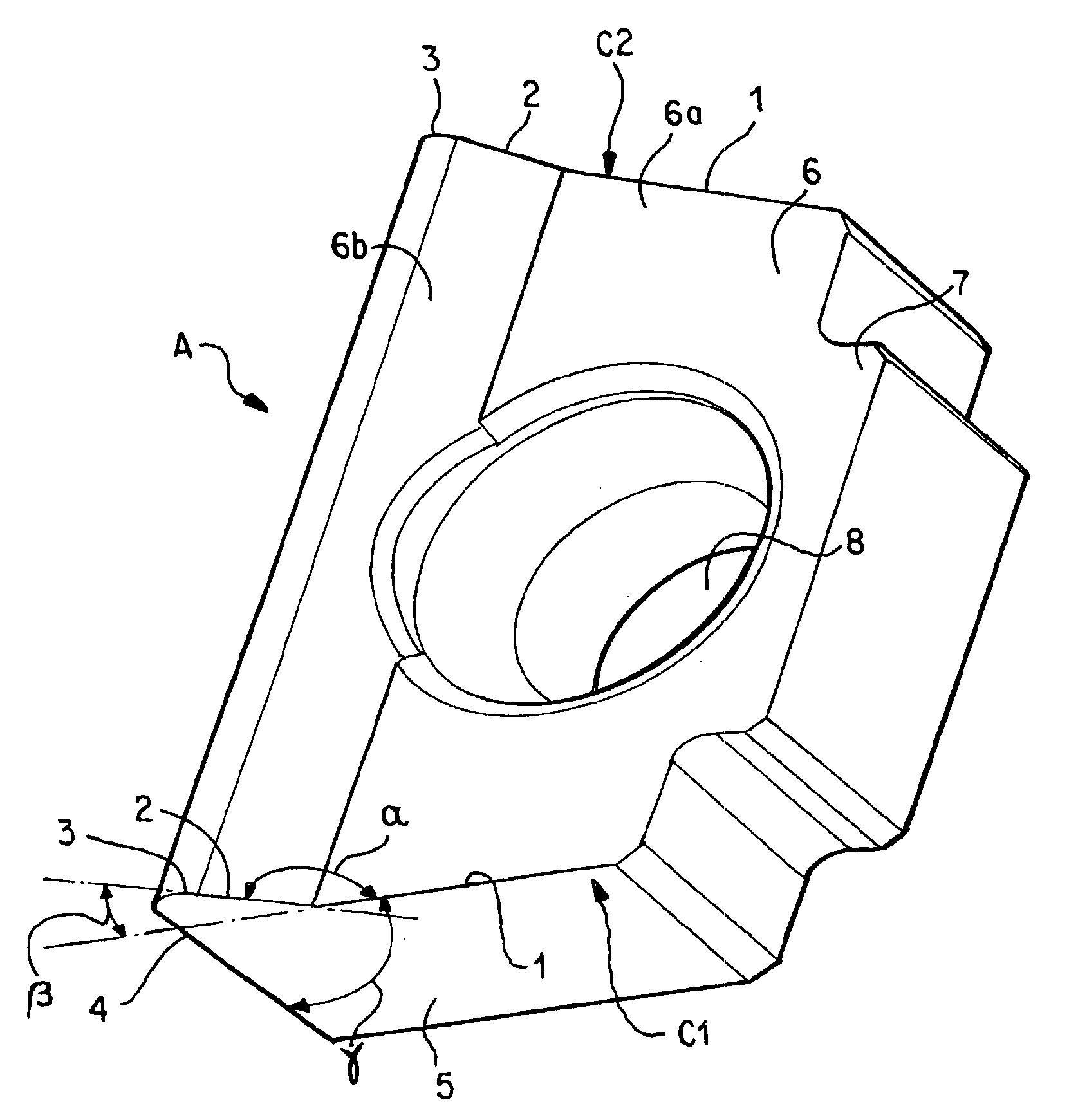
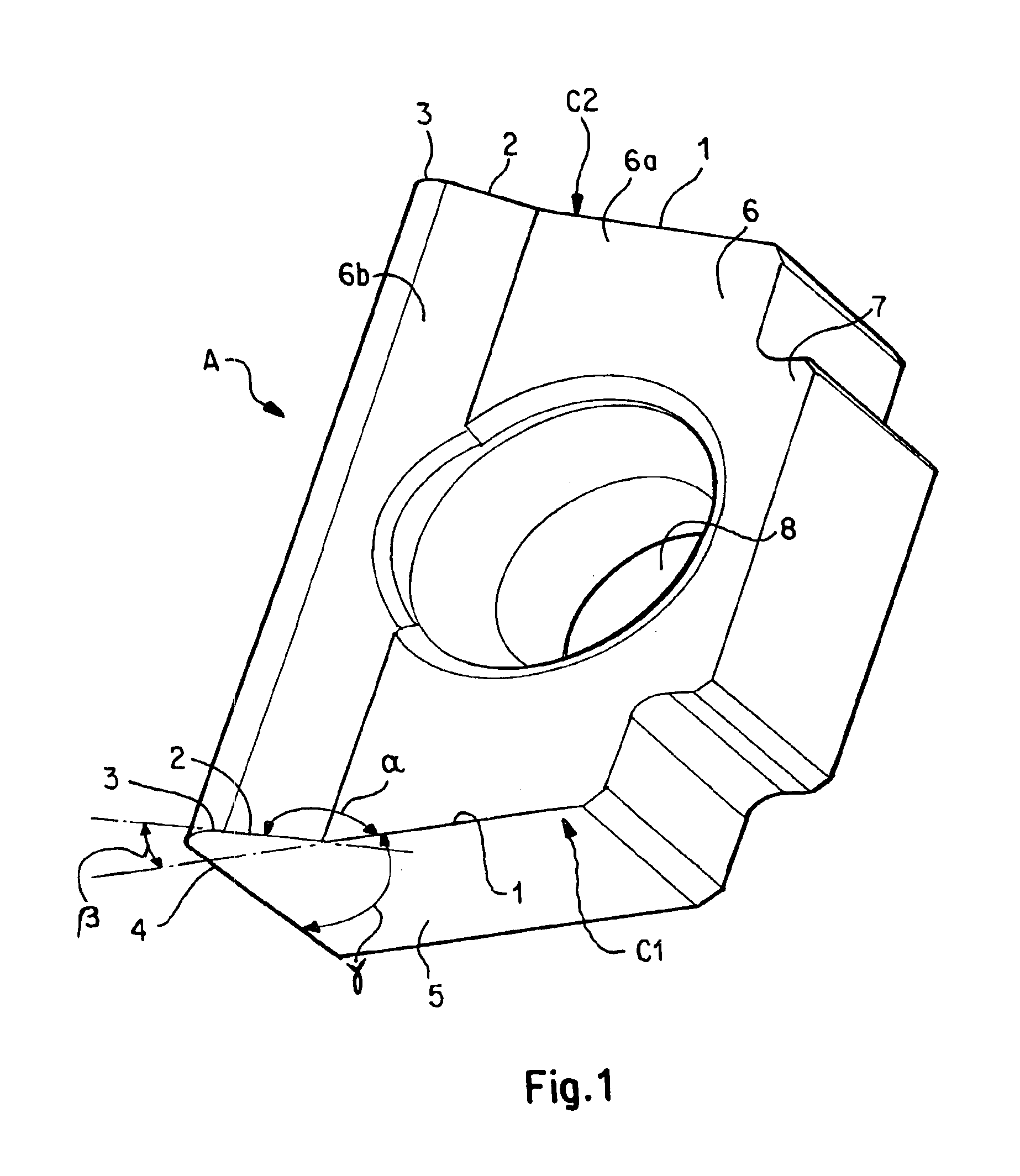
[0034]FIG. 1 shows a perspective view of a first embodiment of a cutting insert A according to the present invention. Roughly approximated, the cutting insert is square, but with some deviations from this basic shape that will be explained hereinafter. The insert comprises a number of surfaces including a top flank 6, a bottom flank 6a and peripheral edge surfaces 5a-5d. Two opposite ones of the peripheral edge surfaces 5a, 5b of the square that are not exactly parallel, but are inclined towards one another at an angle of 16° form faces that adjoin cutting edges 1, 2, 3 that are formed by the transition between the face 5a and the top flank 6 substantially perpendicular thereto. A fixing bore 8 extends perpendicular to, and passes through, the flank 6, which bore is provided for receiving a screw or a screw head for fastening the cutting insert to a milling tool.

[0035]The flank 6 is not a complete planar surface, but instead, in addition to a planar section 6a along an edge extendin...


PUM

PropertyMeasurementUnit
obtuse angleaaaaaaaaaa

Abstract

A cutting insert for milling cam shafts includes first and second surface interconnected by a third surface, and at least one cutting edge. The cutting edge includes a straight first cutting edge section, a straight second cutting edge section, and a generally convex third cutting edge section, all adjoining one another. The first section extends along the junction between the first and third surfaces. The second section extends along the junction and includes a first end adjoining an end of the first section. The second is inclined at an obtuse angle from one end of the first section in a direction away from the third surface. The third section extends along the junction and adjoins a second end of the second section. The third section is of generally convex shape and extends over an angular range greater than 90°. The first, second and third sections lie in the third surface.

Description

BACKGROUND[0001]The present invention relates to a cutting insert, in particular for milling camshafts, with at least one cutting edge composed of several sections. Such cutting inserts have been known in principle for a long time.[0002]The manufacture of camshafts is usually done conventionally in that a camshaft is firstly cast in a mould, wherein the cast camshaft nevertheless does not yet possess sufficient accuracy in its dimensions for it to be used as a camshaft. The camshaft thus manufactured, cast with excess dimensions, is therefore subjected to further stages of finishing. Parts of the camshaft, in particular journals thereof, have an exact circular or cylindrical shape, and a common axis. These parts are as a rule worked or manufactured on a suitable lathe by turning. The cam contours are subsequently milled with so-called disc milling cutters about the periphery of which a large number of cutting inserts are arranged, the combined cutting edge profile of which correspon...

Claims


Application Information

Patent Timeline
Patent Type & Authority Patents(United States)
IPC IPC(8): B23C5/02B23C5/08B23C5/16B23C5/22B23B27/16B23C3/06B23C5/12B23C5/14B23C5/20
CPCB23C5/08B23C5/2213B23C2200/0416B23C2215/16Y10T407/235Y10T407/24Y10T407/2274Y10T407/1936Y10T407/23B23C3/06
Inventor WERMEISTER, GUNTER
Owner SANDVIK INTELLECTUAL PROPERTY AB
Why Eureka
Try Eureka