
Desktop process for producing dental products by means of 3-dimensional plotting

a technology of 3-dimensional plotting and desktop process, which is applied in dentistry, additive manufacturing with solid and fluid, moulds, etc., can solve the problems of requiring a high degree of effort to produce the finished product, the palette of available materials has clearly grown, and the creation of hollow spaces between powder materials cannot be foreclosed, so as to reduce the retention of plaque thereon and achieve good polishing characteristics.

Inactive Publication Date: 2005-09-06
IVOCLAR VIVADENT AG
View PDF6 Cites 107 Cited by
  • Summary
  • Abstract
  • Description
  • Claims
  • Application Information

AI Technical Summary

Benefits of technology

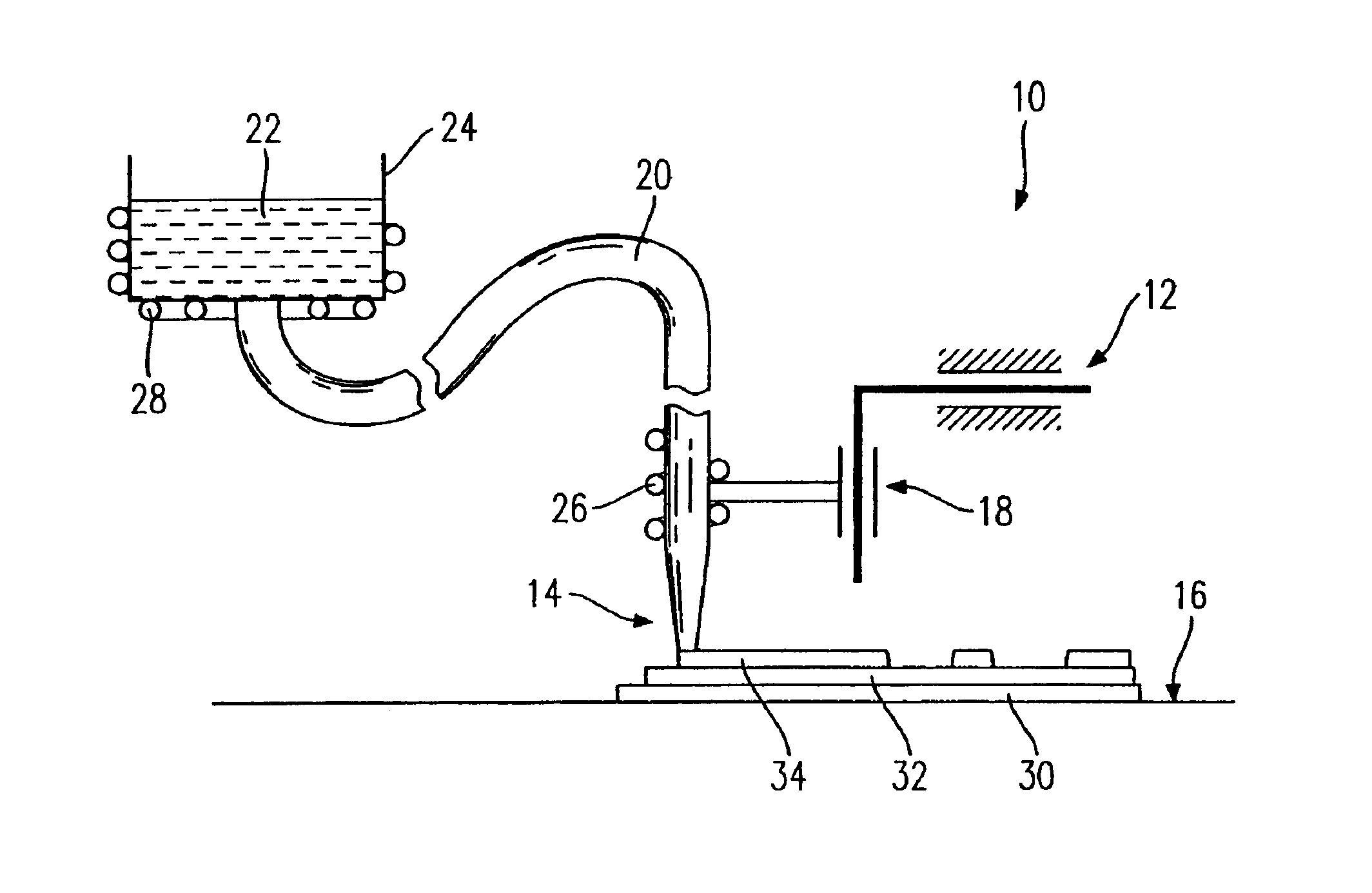
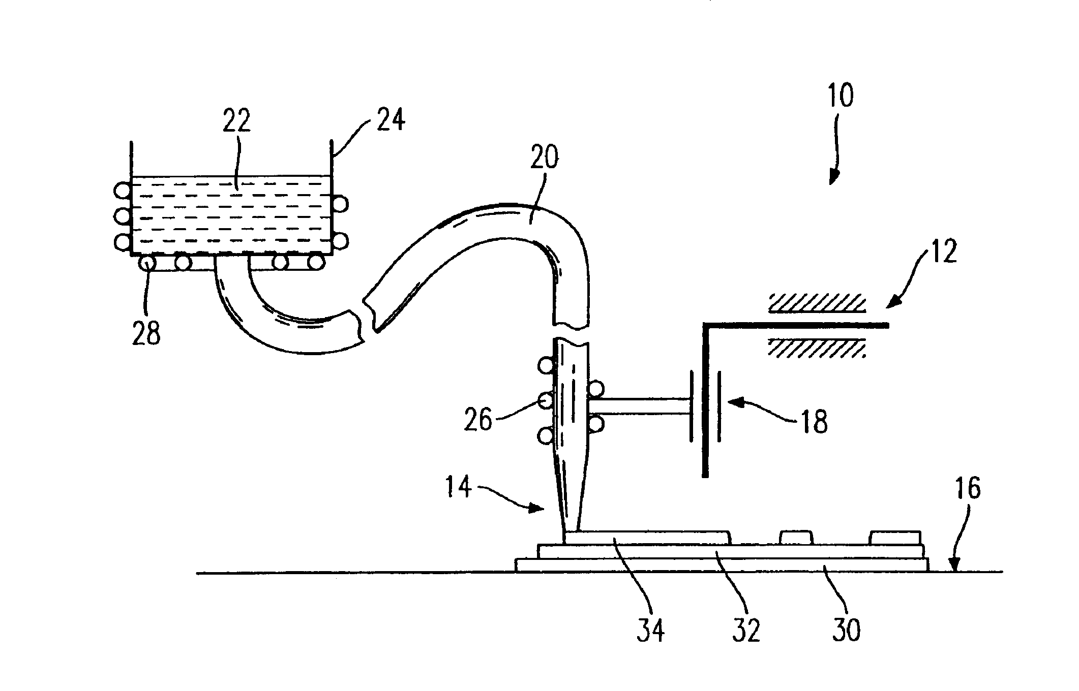
[0012]The present invention offers a solution to the challenge of providing a process for the fabrication of dental products with the use of 3-dimensional plotting such that the fabrication of various types of structured form pieces, out of various materials, is possible and only a low investment cost is required.
[0013]The process of the present invention with the use of 3-dimensional plotting allows the production of dental products on the basis of meltable, condensable, thermal or UV or visible light-hardenable unfilled or filled materials, which are handled by means of a 3-dimensional plotter. It is for the first time possible, with the process of the present invention, to fabricate dental materials on the basis of high viscosity or, respectively, filled, intermediate production materials via a computer supported form or mold free finishing process. This thus permits the construction of 3-D objects in layered manner through a computer controlled cutting away of micro drops or micro cords in a fluid medium or on a firm oversurface. The hardening of the material follows as a function of the material used in the building of the dental object, either through cooling of the melted material, chemical reaction, or polymerization with thermal or, respectively, simultaneous, or thereafter following, irradiation. It is, moreover, possible to effect a complete hardening of the material through a chemical reaction with a fluid medium.

Problems solved by technology

These conventional processes are proven; however, they require a high degree of effort to produce the finished product.
While in the first years of use of such processes, the technically fascinating but cost unfavorable model generating processes predominantly used light hardened acrylic resins (stereolithography), the palette of available materials has clearly grown.
The disadvantage of this process, however, is that the creation of hollow spaces between the powder material cannot be foreclosed.
Moreover, according to the above-noted publication, filled plastic cannot be used as the powder.
As has been noted, this type of process is time consuming while, at the same time, the computer tomography portion is very expensive and is in no way commonly found in dental offices.
A pressure application process of this type is, however, not suitable for all circumstances.
A further problem in the practical realization of dental prostheses by this process is that a control in the articulator must constantly be performed for the positioning of the tooth.
It is in practice not possible to remove a model from such a wax prosthesis in a disturbance-free manner since, at the least, micro back cuts occur and a wax model material typically exhibits, even at room temperature, a reduced hardness relative to, for example, plaster.
Although this process admittedly enables a decidedly exact fabrication of the dental replacement product, the fabrication process requires significant resources and requires an electronically controllable machine tool, which performs the desired work by means of a cutting process.
This process suffers from a number of disadvantages, however, in that remnants and debris are created which cannot be tolerated in a dental office practice.
Moreover, the thus fabricated dental replacement product must frequently be coated by conventional processes, as the material produced does not meet the aesthetic requirements for such dental replacement products.
Due to the need to effect a complete through hardening of the material, it is necessary to use significantly small material pieces, whereby the fabrication process takes a correspondingly long time.
In this regard, however, the choice of suitable materials is limited to only a few thermoplastic materials such as, for example, ABS.
A further disadvantage is that a cord of suitable dimension of the material to be applied must first be produced which can then be subsequently applied through the nozzle.

Method used


Image

  • Desktop process for producing dental products by means of 3-dimensional plotting
  • Desktop process for producing dental products by means of 3-dimensional plotting

Examples


example 1

Treatment to Completion of an Inlay Comprised of a Light Hardenable, Low Viscosity Dental-Like Filling Material

[0037]The inlay was fabricated with a conventional low viscosity, light hardenable film (Tetric Flow available from Ivoclar-Vivadent AG). To fabricate the inlay, data concerning the cavity was transferred into the computer controlled plotting unit. The fabrication of the inlay then followed by computer controlled cutting away of micro points of the material disposed on a metal oversurface. The hardening of the deployed materials was accomplished by a light source disposed parallel to the nozzle emitting light in a wavelength range of 400 to 500 nm. The construction of the cavity was conducted in a manner such that a micro point was plotted every 10 seconds. In the interval between the plots of every two successive points, the outlet opening of the nozzle was closed and the above-noted light source was activated to effect the hardening.

example 2

[0038]The fabrication of the inlay of Example 1 above was repeated with the use of another conventional dental like film (Heliomolar Flow, Tetra Chroma and Ariston AT available from Ivoclar-Vivadent AG).

example 3

The Fabrication of an Inlay Comprised of a Light Hardenable, Short Length Glass Fiber Filled Monomer Mixture

[0039]A short length glass fiber filled monomer mixture combined in the hereafter described combination was used to fabricate the inlay. The following data is given as percent by weight.[0040]30% short length glass fibers (fabricated by Schott) having an average length of 115 mm[0041]29% Bisphenol—A—Diglycidyldimethacrylate (Bis-GMA)[0042]26% 7,7,9-Trimethyl-4,13-dioxo-3,14-dioxa-5,12-diazahexadecane-I,16-dioxy-di-methacrylate[0043]14% Triethyleneglycoldimethacrylate[0044]1% low molecular stabilizers, additives, and initiators

[0045]The fabrication of the short length glass fiber filled monomer mixture included a working in of the short length glass fibers into the monomer mixture by means of a moving tool.

[0046]The inlay was thereafter constructed by use of the computer controlled plotting unit to conduct a computer controlled cutting away of micro cords of the selected materi...


PUM

PropertyMeasurementUnit
diameteraaaaaaaaaa
diameteraaaaaaaaaa
diameteraaaaaaaaaa

Abstract

A process for fabricating dental form pieces for dental restoration and replacement parts is provided and includes the step of applying a material, on a firm support or a fluid medium, by a three dimensional plotting technology in a layer by layer manner. The material has micro cords and / or micro drops which include at least one of a meltable, polymerizable, polycondensable, and polyaddable constituent element that is an unfilled monomer, a reinforced monomer, oligomer, polymer, or a ceramic element. The process also includes the step of hardening the applied material by cooling of the material, chemical reaction, polymerization with thermal handling, or polymerization by irradiation of the material with UV or visible light.

Description

[0001]This application claims the benefit of Provisional Application No. 60 / 289,922, filed May 10, 2001.BACKGROUND OF THE PRESENT INVENTION[0002]The present invention relates to a process using 3-dimensional plotting for producing dental products by which meltable, condensable, thermal or UV or visible light-hardenable unfilled or filled materials are handled by means of a 3-dimensional plotter.[0003]Traditional multiple step molding and casting processes are still overwhelmingly used today for the production of dental replacement products or portions of a dental restoration such as inlays, onlays, bridges, crowns, or prostheses. In this regard, the production of the individual dental form pieces follows in further steps in conventional ways. These conventional processes are proven; however, they require a high degree of effort to produce the finished product. With a view toward ameliorating this effort, a number of processes have been developed, within recent years, with the goal o...

Claims


Application Information

Patent Timeline
Patent Type & Authority Patents(United States)
IPC IPC(8): A61C13/00A61K6/083A61K6/02B29C67/00A61C19/00
CPCA61C13/0004A61K6/083B29C67/0081C08L33/00C08L25/04A61C13/0019A61C19/003B29L2031/7536B29C64/165B33Y80/00A61K6/887A61C13/0003B29C64/386
Inventor MOSZNER, NORBERTBURGATH, ARMINMULHAUPT, ROLFSALZ, ULRICHRHEINBERGER, VOLKERLANDERS, RUDIGER
Owner IVOCLAR VIVADENT AG
Learn More