Electrical impedance tomography

a technology of electric impedance and tomography, applied in the field of electric impedance tomography, can solve the problems of difficult to present data with high repeatability from a sensor with discrete electrodes, non-uniform and inability to provide a correct measurement from a fluid with a discontinuous phase of electrical conductivity. achieve the effect of improving the distribution of imaging sensitivity

Inactive Publication Date: 2005-09-06
LEEDS THE UNIV OF
View PDF13 Cites 94 Cited by
  • Summary
  • Abstract
  • Description
  • Claims
  • Application Information

AI Technical Summary

Benefits of technology

[0008]The object of the invention is to provide a sensing method and apparatus with an improved imaging sensitivity distribution for measuring the electrical impedance distribution in a principle flow with an electrically continuous or discontinuous phase and a practically applicable accurate reconstruction algorithm for flow measurement.
[0012]The sensor geometry and its conductivity can be optimized for the objective that the condition number of the sensitivity matrix becomes less and the sensitivity field becomes more homogenous.

Problems solved by technology

Firstly, it can not provide a correct measurement from a fluid with a discontinuous phase of electrical conductivity since some of these electrodes have lost their electrical contact with the conductive phase of the fluid, e.g. a half filled horizontal stratified flow or a foam construction with a large bubbling formation [M. Wang and C. J. Young, Chem. Eng. Science, 54(5), 1999].
Secondly, it generates a very non-uniform distribution of the imaging sensitivity because high dense currents are always present at the domains near to the current injecting and sinking electrodes.
In addition, it is difficult to present data with high repeatability from a sensor with discrete electrodes since the unstable performance of the contact impedance or the electrode-electrolyte interfaces.
Finally, the intrusive construction of the electrodes in these sensors has obvious difficulties from its installation for satisfying most industrial environments.

Method used


Image

  • Electrical impedance tomography
  • Electrical impedance tomography
  • Electrical impedance tomography

Examples


Embodiment Construction

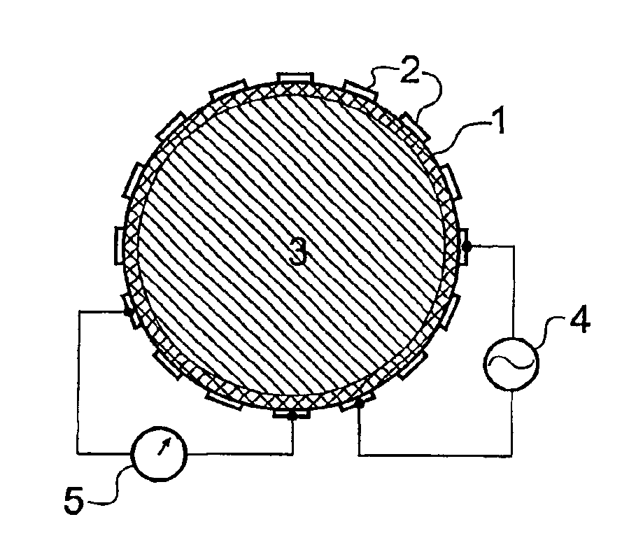
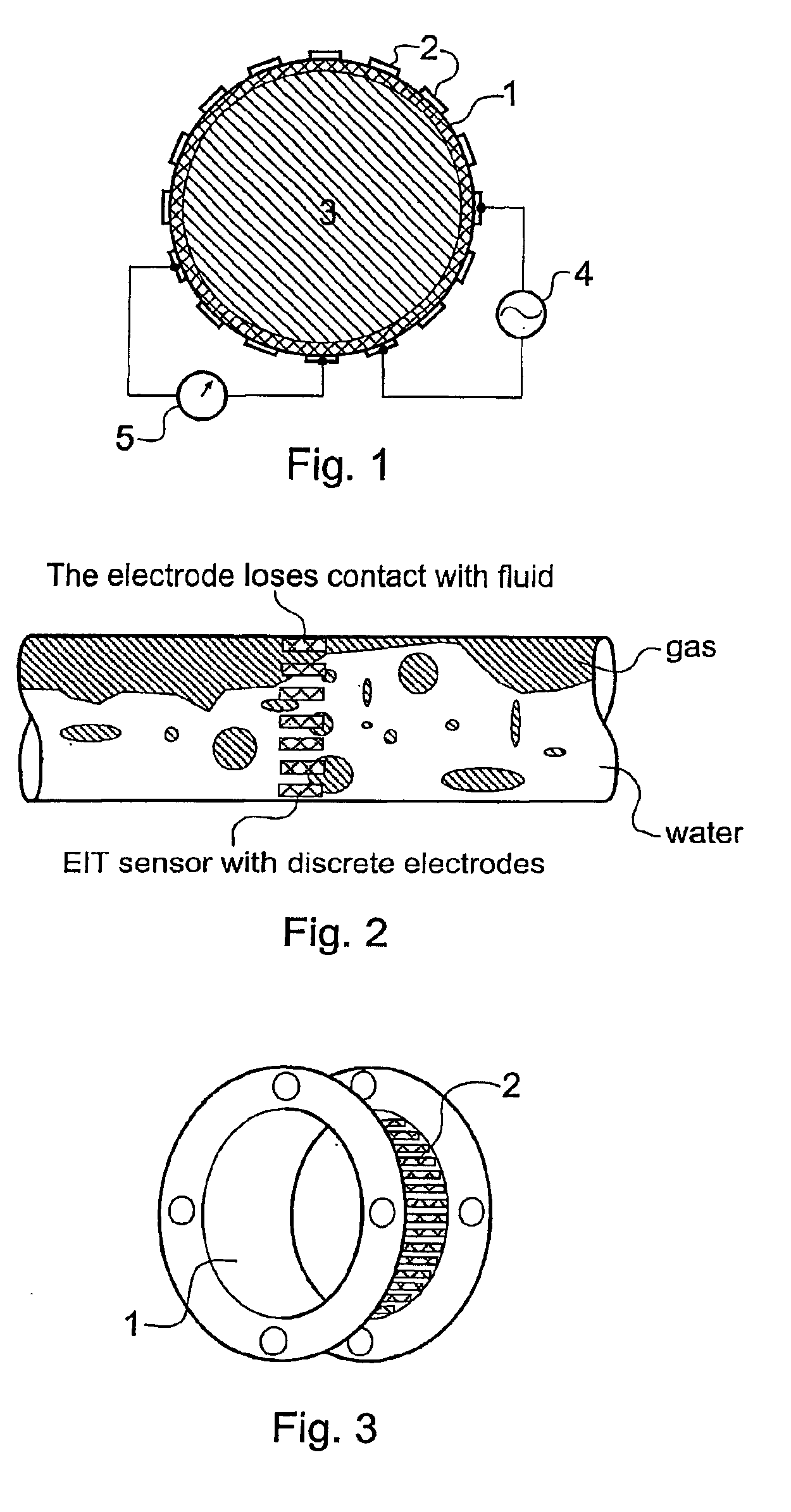
[0043]The electrically conductive ring sensor basically consists of an electrically conductive ring 1, a number of electrical contacts 2, a target content 3, a number of electrical excitation sources 4 and a number of voltage measurement devices 5 [FIG. 1].

[0044]The electrically conductive ring 1 is made of solid substances such as a kind of metals or alternatively, other electrically conductive materials such as conductive rubber or ceramic-metal with a conductivity value much higher than that of the content 3 to be measured. The electrically conductive ring acts as an ‘continuous electrode’ to distribute the electrical current flow and generate an electric field for mapping the impedance distribution of the content 3 due to applying currents from the metallic contacts 2. The metallic contacts 2 are embedded into the electrically conductive ring in good electrical contact with the outside wall of the electrically conductive ring. The size of these contacts 2 may be very small since...


PUM

PropertyMeasurementUnit
conductivityaaaaaaaaaa

Abstract

Methods and apparatus are provided for obtaining a representation of the distribution of electrical impedance within a multiphase flow with an electrically continuous or discontinuous principle flow contained within an electrically conductive solid ring electrode, including providing a plurality of mutually spaced electrical contacts mounted at the outside wall of the ring and electrically contacting with the ring, applying currents or voltages to the ring from the electrical contacts, generating a more homogeneous electric field distribution within the material, measuring voltage or current distribution alone the ring from other electrical contacts, relatively intensifying the imaging sensitivity at the central area of the sensing domain using a π / 2 angle sensing strategy and reconstructing the representation of the impedance distribution using CG method with an error processing strategy.

Description

RELATED APPLICATIONS[0001]The present application is a 35 U.S.C. §371 national phase application of PCT International Application No. PCT / GB01 / 05636, having an international filing date of Dec. 28, 2001, and claiming priority to Great Britain Patent Application No. 0031854.3, filed Dec. 30, 2000 and Great Britain Application No. 0120772.9, filed Aug. 25, 2001, the disclosures of which are incorporated herein by reference in their entireties. The above PCT International Application was published in the English language and has International Publication No. WO 02 / 053029 A1.BACKGROUND OF THE INVENTION[0002]This invention relates to a method of measuring the distribution of electrical impedance of a multi-phase flow using an electrically conductive ring electrode, and to a method of determining the internal structure of a body which utilises such a method and a computer programme product adapted for determining the internal structure of a body.[0003]The invention further relates to an a...

Claims


Application Information

Patent Timeline
Patent Type & Authority Patents(United States)
IPC IPC(8): A61B5/053G01N27/20G01N27/24
CPCG01N27/24A61B5/0536G01N27/20
Inventor WANG, MIYIN, WULIANG
Owner LEEDS THE UNIV OF
Why Eureka
Try Eureka