
Self-aligned transition between a transmission line and a module

a transmission line and self-aligning technology, applied in the direction of printed circuit aspects, one-port networks, waveguide type devices, etc., can solve the problems of high connection precision requirements, large insertion loss, and extremely sensitive waveguide-to-microstrip transitions to geometry errors, etc., to achieve easy and precise connection of transmission lines, easy and precise connection of modules, and simple and precise connection of transmission lines

Inactive Publication Date: 2005-09-06
WSOU INVESTMENTS LLC
View PDF2 Cites 84 Cited by
  • Summary
  • Abstract
  • Description
  • Claims
  • Application Information

AI Technical Summary

Benefits of technology

[0004]It is therefore an object of the invention to provide a method permitting a simple and precise connection of a transmission line with to some other module, to provide a module that can be connected easily and precisely to a transmission line, to provide an intermediate element that can be used for an easy and precise connection of a module to a transmission line and to provide a system comprising the transition of a transmission line to a module formed by a precise connection.
[0008]The invention proceeds from the concept that a precise connection between a transmission line and another module can be realised by taking advantage of the behaviour of solder particles under reflow treatment. It is known to those skilled in the art that solder balls and other solder particles are self-aligning under reflow treatment due to surface tension phenomena in the solder material. Accordingly, under reflow treatment, slight misalignment is corrected by the surface tension forces, making it unnecessary to use any additional procedures for alignment. When using a reflow soldering of solder particles for transitions between transmission lines and modules, as proposed by the invention, a very precise connection of transmission line and module can be achieved, thereby reducing considerably the resulting insertion losses.
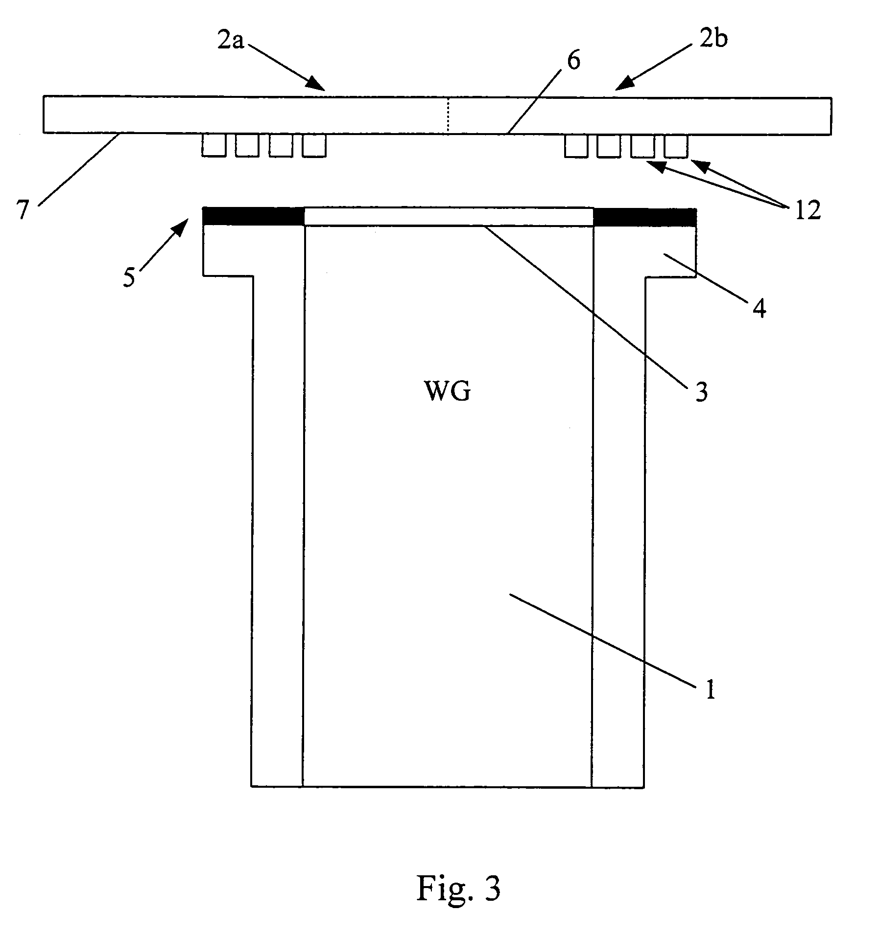
[0010]Two basic alternatives are proposed for the method, the module, the transmission line and the system according to the invention, both alternatives being based on the above described principle. According to the first alternative, module and transmission line are connected or destined to be connected directly to each other. According to the second alternative, module and transmission line are connected or destined to be connected to each other via an intermediate element, for example a printed circuit board. The second alternative has the advantage of a facilitated application of the soldering pads and of a facilitated connection by reflow soldering.

Problems solved by technology

Usually, the requirements on the precision of the connection are high, since even small deviations will degrade the performance resulting in a considerable insertion loss.
Especially waveguide-to-microstrip transitions are extremely sensitive to geometry errors.
Such methods lead, however, to rather inaccurate results and the tolerances can be quite large so that the requirements cannot be met satisfactorily.
To connect transmission lines to other modules mechanically also constitutes an extremely difficult and time-consuming assembly phase.

Method used


Image

  • Self-aligned transition between a transmission line and a module
  • Self-aligned transition between a transmission line and a module
  • Self-aligned transition between a transmission line and a module

Examples


Embodiment Construction

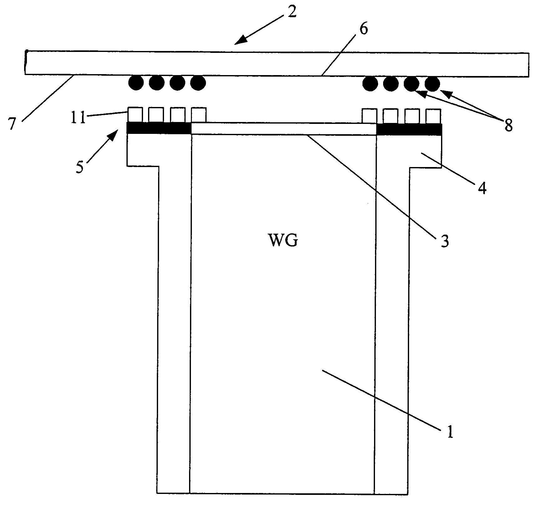
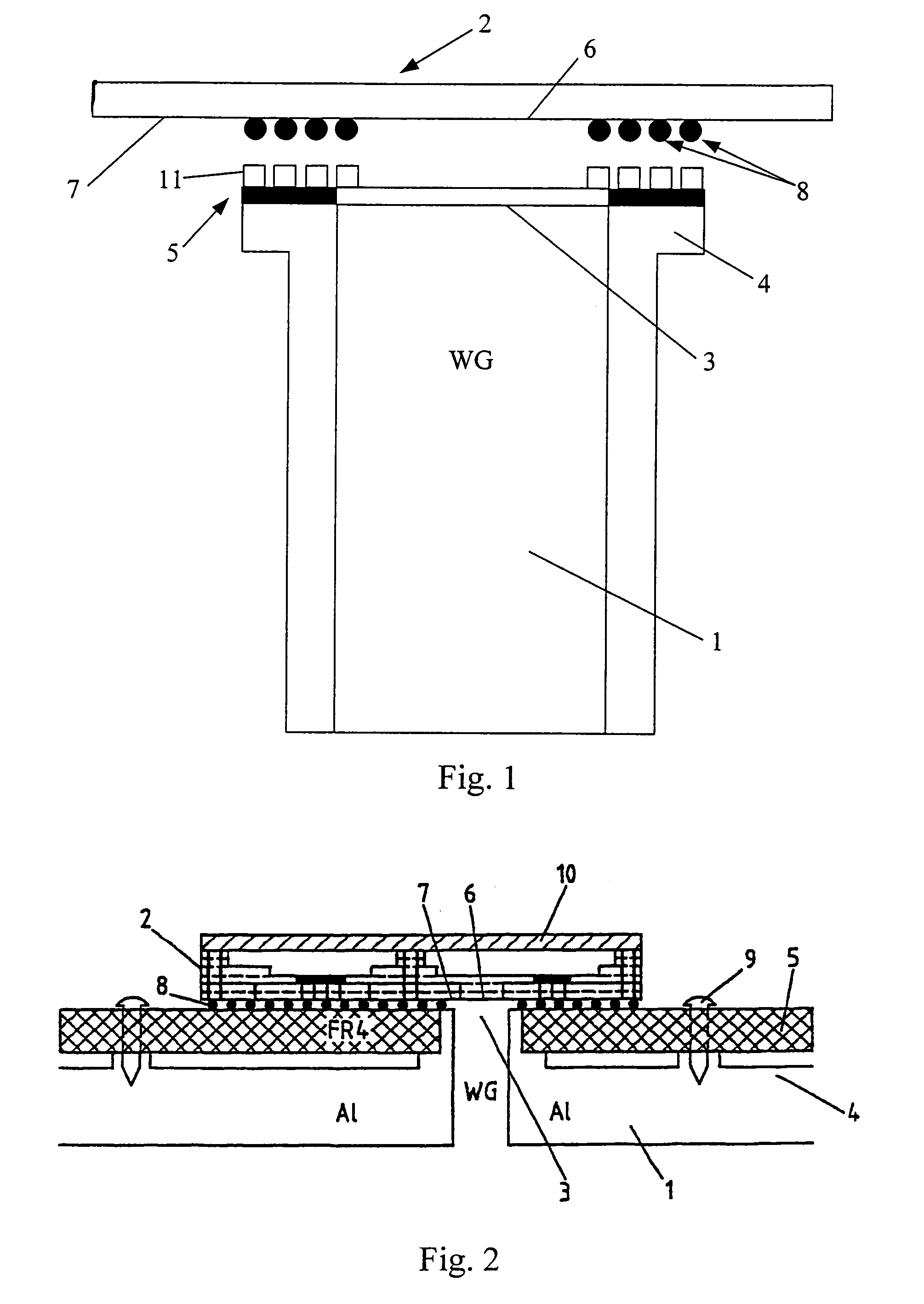
[0018]FIG. 1 illustrates the principle of the invention. To this end, it shows a sectional view of the elements of a system according to the invention before being connected.

[0019]A partly depicted rectangular waveguide 1 forms the transmission line of the system. At its open end 3, the waveguide 1 has an enlarged rim 4, on which an intermediate element 5 with a middle-opening has been fixed.

[0020]Above the open end 3 of the waveguide 1, a simple microstrip structure 2 is depicted. This microstrip 2 represents a system module that is to be connected to the waveguide 1. The microstrip 2 has an aperture 6 in its ground plane 7, by which it is to be coupled with the open end 3 of the waveguide 1 in order to form a transition.

[0021]The microstrip 2 is provided at its ground plane 7 with solder balls 8 in a Ball Grid Array (BGA) or a similar type of joining technique, the solder balls 8 being arranged closely around the aperture 6 in the ground plane 7.

[0022]On top of the intermediate el...


PUM


Abstract

The invention relates to a method for forming a self-aligned transition between a transmission line (1) and a module (2) to be connected to said transmission line (1). The invention equally relates to such a module (2), to such a transmission line (1), to an intermediate element (5) possibly to be positioned between such a module (2) and such a transmission line (1), and finally to a system comprising such a transition. In order to enable a simple and precise connection of a transmission line (1) with some other module (2), it is proposed to use matching solder particles (8) and soldering pads on module (2) and transmission line (1) or intermediate element (5) respectively, and to apply a reflow treatment to the joined elements (1) and (2) or (5) and (2), thereby forming a self-aligning connection. The invention is to be applied particularly to waveguide-to-microstrip transitions.

Description

FIELD OF THE INVENTION[0001]The invention relates to a method for forming a self-aligned transition between a transmission line and a module to be connected to the transmission line. The invention equally relates to such a module, to such a transmission line, to an intermediate element possibly to be placed between such a module and such a transmission line, and finally to a system comprising such a transition.BACKGROUND OF THE INVENTION[0002]Transitions between transmission lines and other modules are employed in diverse systems. A common connection is, for example, a waveguide-to-microstrip transition. Usually, the requirements on the precision of the connection are high, since even small deviations will degrade the performance resulting in a considerable insertion loss. Especially waveguide-to-microstrip transitions are extremely sensitive to geometry errors. Simulations show that a length difference of only 50 microns in a microstrip can result in an insertion loss increase of 0...

Claims


Application Information

Patent Timeline
IPC IPC(8): H01P5/107H01P5/10H05K1/02H05K3/34
CPCH01P5/107H05K1/0243H05K1/0272H05K3/0061H05K3/3436H05K2201/10734H05K2203/048H01L2924/15311H01L2924/16195
Inventor JOKIO, KALLESALMELA, OLLIKOIVISTO, MARKKUSAARIKOSKI, MIKKOARSLAN, ALI NADIR
Owner WSOU INVESTMENTS LLC
Learn More