To interlace or not to interlace has been a contentious issue between the television and computer communities.
However, in addition to the loss of vertical resolution, interlacing results in many well-known artifacts such as line
flicker.
Another major flaw of interlacing is that it complicates many images
processing tasks, especially scanning format conversion.
The
consumer wants to be able to view a standard
NTSC signal from broadcast or VCR in the new HDTV, but because of the nature of HDTV, the artifacts in a standard
NTSC signal are becoming more visible and annoying when displayed on in high-definition television video.
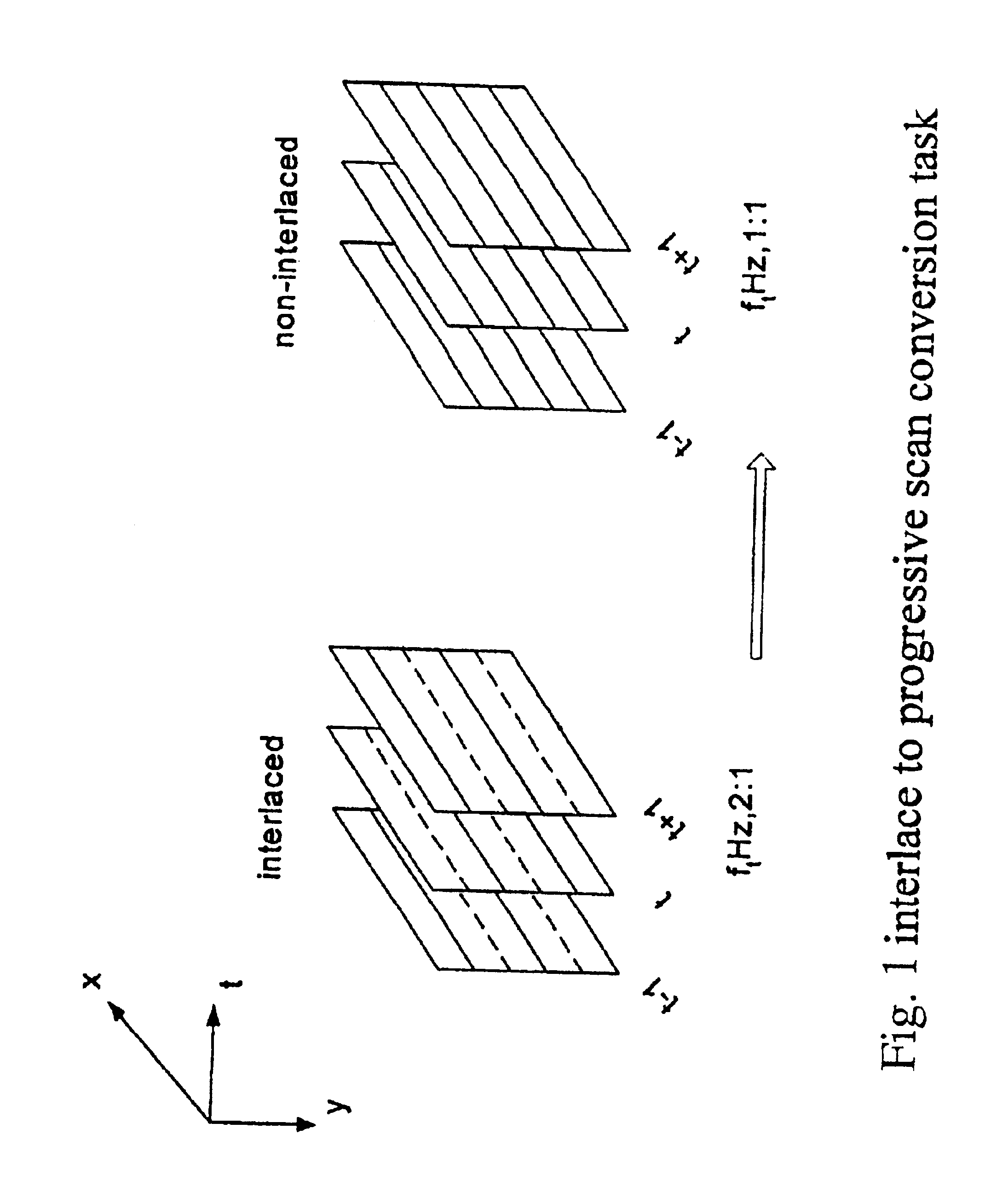
From the mathematical perspective, the process of interlace-to-
progressive scan conversion is a problem in linear up-sampling conversion.
Despite years of research, most of the algorithms are only suitable for specific image characteristics.
The challenge, therefore, is to implement an
algorithm that can be adapted to various image characteristics.
Unfortunately this is not a simple problem since interlace-to-
progressive scan conversion, suffers from some fundamental problems.
For example, though a few algorithms can adapt to various image characteristics, most of them are too complicated to implement in real applications.
However, due to lack of prefiltering in the interlacing process, the interlace-to-progressive
scan conversion process is not as simple as it looks like.
There are two major problems confronting interlace-to-progressive
scan conversion processes.
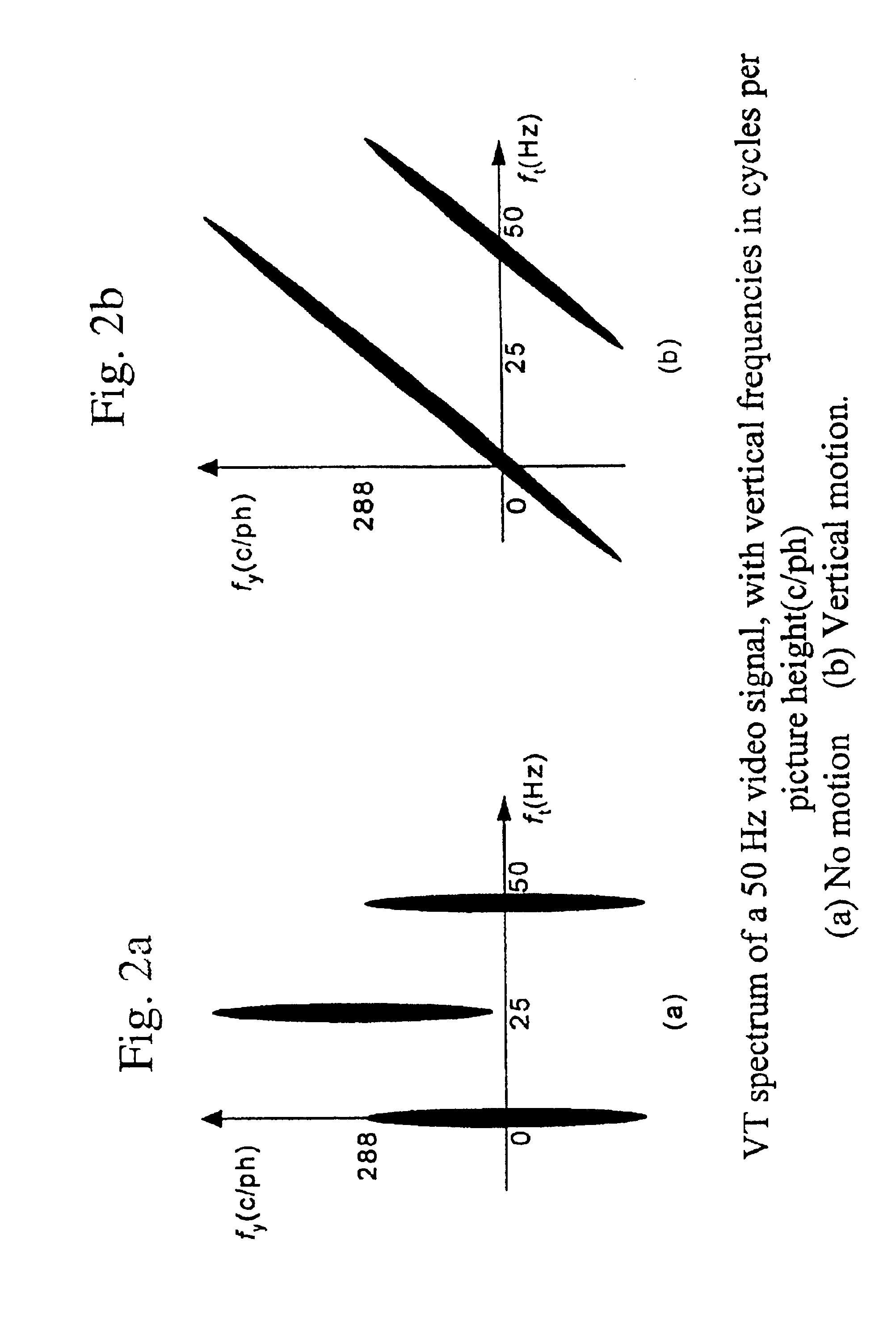
The first is that TV signals do not fulfill the demands of the sampling theorem, i.e., it doesn't satisfy the Nyquist criteria.
Hence, some of the information is lost during the interlaced sampling process.
From
frequency domain point of view, some of the higher frequencies still lie outside the sampling frequency, and thus cause
aliasing.
The second major problem is that the temporal frequencies at the
retina of an observer have an unknown relation to the scene content.
Consequently, suppression of such apparently high and less relevant frequencies results in significant blurring for this viewer.
In most cases, motion adaptive prefiltering is not feasible, and interlacing is done without any prefiltering.
Clearly, interlace-to-progressive
scan conversion is a spatio-temporal problem.
These methods are considered outdated within the TV-product
community.
However, this suppresses the higher part of the
baseband spectrum as well which causes the output signal to be blurred.
In general, purely spatial filters cannot discriminate between
baseband and repeat spectrum regardless of their length.
This causes
serration of moving edges, which is a very annoying artifact.
Unlike
signal processing for audio signals, this will increase the storage requirement significantly.
Therefore it is economically unattractive.
Furthermore, they still cannot discriminate between
baseband and repeated spectra.
The major drawback of median filtering is that it distorts vertical details and introduces
alias.
Unfortunately, due to
noise, the difference signal doesn't become zero in all parts of the picture that lack motion.
Some systems have additional problems; for example,
chrominance streams cause nonstationarities in color regions, interlace causes nonstationarities in vertical detail parts and timing
jitter of the sampling
clock is particularly harmful in horizontal detailed areas
Even with an
adaptive switching /
fading function, it is still difficult to make a function that can adapt to any kind of image.
The computational complexity of the
algorithm is very low and requires memory for only one field instead of an entire frame.
For example,
noise—or more fundamentally,
alias—can negatively influenced the decision.
The problem of alias however, still remains.
This problem arises if the
motion vector used to modify coordinates of pixels in a neighboring field does not point to a pixel on the interlaced sampling grid.
In the vertical domain, however, the demands for applying the sampling theorem are not satisfied, prohibiting correct interpolation.
This is not recommended, however, as the
motion vector loses validity by extending it too far.
The algorithm implicitly assumes uniform motion over a two-fields period, which is a drawback.
Furthermore, the robustness to incorrect motion vectors is poor, since no protection is provided.
Thus errors originating from one output frame can propagate into subsequent output frames.
This is inherent to the recursive approach and is the worst drawback of this approach.
Aliasing at the output of the deinterlaced results in nonstationarity along the motion trajectory.
Consequently, the adaptive-recursive approach, similar to the time-recursive approach, has the risk of error propagation as its main
disadvantage.
Pel-
recursive algorithms have rarely been used because they are inherently complex and quite difficult to implement.
Another problem with PRAs is that the
motion estimation algorithms sometimes run into convergence problems.
In practice this is difficult because there are numerous processes which can change the luminance gradient.
Various illuminations, such as when an object moves into shade, also cause difficulty.
The process can be assisted by
recursion, in which the motion is estimated over a larger number of fields, but this will result in problems directly after a scene change.
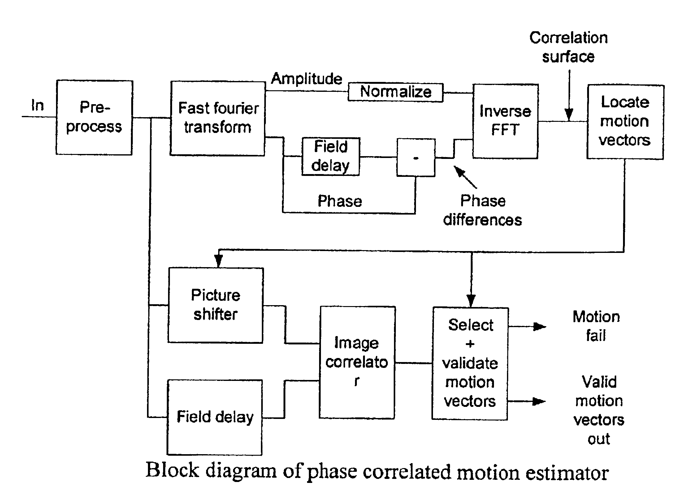
Although the matching process is simplified by adopting
phase correlation, the Fourier transforms themselves require complex calculations.
The high performance of
phase correlation would remain academic because it's too difficult to implement, were it not for an important assumption about the
range of motion speeds.
However this is impractical and it requires a lot of overhead
processing.
In most cases it's nearly impossible to get a similar block from the previous field.
The Cross-correlation is the best method in the sense that it produce less error, but it requires a lot of computation, which makes it impractical to implement.
If the window is not big enough, there is a chance that the MV (x,y,t) that we get is not optimal, especially in the case of a very fast moving objects.
Though brute search BMAs give a global optima result, it requires more complex circuitry or more time to process.
The complex circuitry makes the price of these ICs impractical for most applications.
In one-dimensional recursive searching, like one-at-a-time searching, the resulting smoothness of these algorithms is insufficient.
This can cause strong deviation from the prediction, like inconsistencies in the velocity field, as the vector
selection criterion applied in block matching (minimum match error) cannot guarantee returning true motion vectors.
The fundamental difficulty with a one-dimensionally recursive algorithm is that it cannot cope with discontinuities in the velocity plane.

