Continuous scan tomosynthesis system and method

Inactive Publication Date: 2005-09-06
GENERAL ELECTRIC CO
View PDF9 Cites 150 Cited by
  • Summary
  • Abstract
  • Description
  • Claims
  • Application Information

AI Technical Summary

Benefits of technology

[0008]Briefly, in accordance with one embodiment of the invention, an imaging system performing tomosynthesis on a region of an object comprises an x-ray source, motion controller, an x-ray detector and a processing unit. The x-ray source is positioned at a predetermined distance from the object and continuously moves along a path relative to the object. The x-ray source transmits x-ray radiation through the region of the object at a plurality of predetermined locations along the path while the x-ray source is continuously moving along the path relative to the object. The motion controller is coupled to th

Problems solved by technology

Another problem with the step and shoot approach is images generated are blurred due to system vi

Method used


Image

  • Continuous scan tomosynthesis system and method
  • Continuous scan tomosynthesis system and method
  • Continuous scan tomosynthesis system and method

Examples


Embodiment Construction

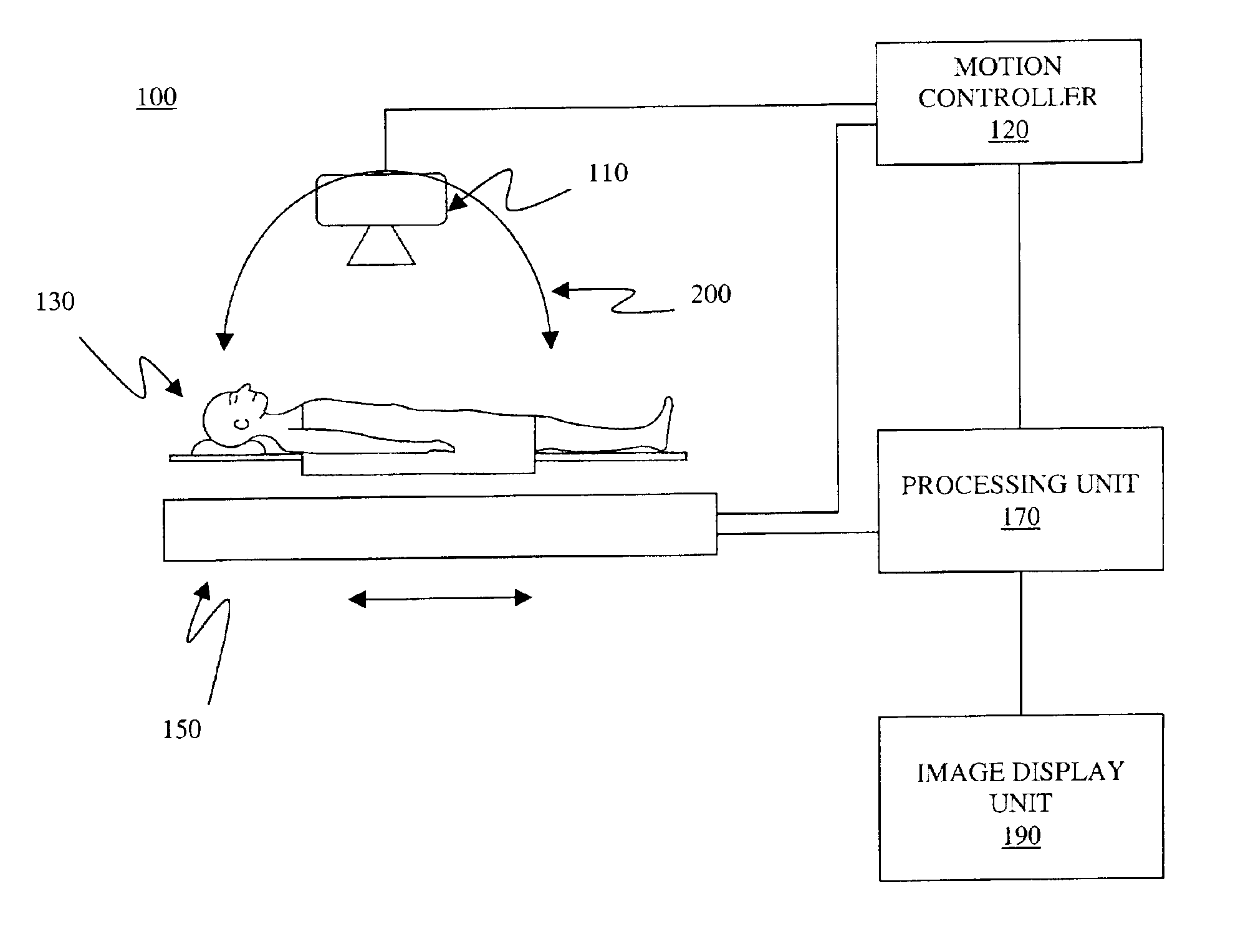
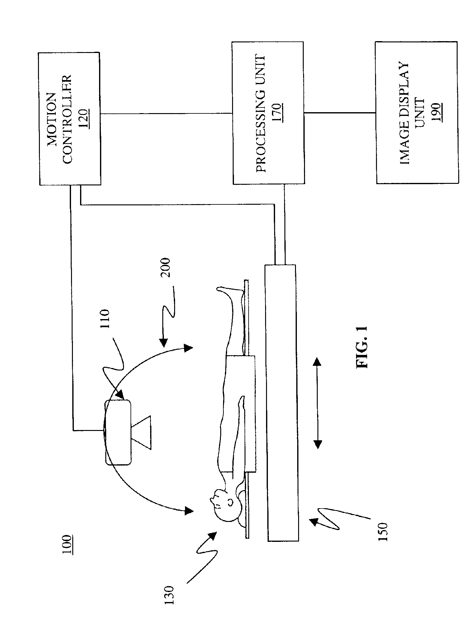
[0016]As shown in FIG. 1, an imaging system 100 includes an x-ray source 110 coupled to a motion controller 120. A processing unit 170 is coupled between the motion controller 120, x-ray detector 150 and the image display unit 190. It should be appreciated that the processing unit 170 can comprise a microprocessor, central processing unit, a personal computer, a workstation, a mini-computer, a mainframe computer or a supercomputer. It should also be appreciated that the motion controller 120 can be included in the processing unit 170 as software using a command language for movement of the x-ray source 110. It should further be appreciated that the processing unit 170 can be coupled to the motion controller 120, x-ray detector 150 and the image display unit 190 via, for example, a telephone or cable network, an ethernet, a local area network (LAN), or a wide area network (WAN), an integrated services digital network (ISDN), or a digital subscriber line (DSL). It should also be appre...


PUM


Abstract

An imaging system for performing tomosynthesis on a region of an object comprises an x-ray source, motion controller, an x-ray detector and a processing unit. The x-ray source is positioned at a predetermined distance from the object and continuously moves along a path relative to the object at a plurality of predetermined locations. The x-ray source transmits x-ray radiation through the region of the object. The motion controller is coupled to the x-ray source and continuously moves the x-ray source along the path relative to the object. The x-ray source minimizes vibration in the imaging system due to continuous movement. The x-ray detector is positioned at a predetermined distance from the x-ray source and detects the x-ray radiation transmitted through the region of the object, thus acquiring x-ray image data representative of the region of the object. The processing unit is coupled to the x-ray detector for processing the x-ray image data into at least one tomosynthesis image of the region of the object.

Description

STATEMENT REGARDING FEDERALLY SPONSORED RESEARCH & DEVELOPMENT[0001]The United States Government may have certain rights in this invention pursuant to the Office of Naval Research / Henry M. Jackson Foundation contract Number 22287 awarded by the U.S. Navy.BACKGROUND OF THE INVENTION[0002]The present invention relates generally to tomosynthesis systems, and more specifically to a system and method for continuous scanning in tomosynthesis systems.[0003]Tomosynthesis systems are often used in the field of medicine to generate three-dimensional (3D) images of an object. A typical tomosynthesis system comprises an x-ray source, an x-ray detector, motion controller and a processing circuit. The x-ray source is moved along a path and projects x-rays on the object, usually a patient. The x-ray detector detects the x-rays and generates a corresponding tomosynthesis data set comprising projection radiographs. The processing unit processes the projection radiograph to generate a 3D image of the...

Claims


Application Information

Patent Timeline
IPC IPC(8): G01N23/02G01N23/04A61B6/02
CPCA61B6/025A61B6/4452G01N23/04A61B6/4208A61B6/588G01N23/044
Inventor CLAUS, BERNHARD ERICH HERMANNKAPUR, AJAYEBERHARD, JEFFREY WAYNE
Owner GENERAL ELECTRIC CO
Why Eureka
Try Eureka