Spherical bearing and method for manufacturing the same

a technology of spherical bearings and bearings, which is applied in the direction of pivotal connections, rotary machine parts, mechanical equipment, etc., can solve the problems of difficult to achieve smooth and light movement, resin sheet is likely to wear, and the movement of the ball section is somewhat heavy, so as to prevent biased wear of the ball section and reduce labor and cost

Inactive Publication Date: 2005-09-13
THK CO LTD
View PDF22 Cites 19 Cited by
  • Summary
  • Abstract
  • Description
  • Claims
  • Application Information

AI Technical Summary

Benefits of technology

[0018]Further, while the resin liner may be molded separately from the ball section and attached to the ball section later, it is preferable, from the viewpoint of reduction of labor and cost, to mold the resin liner directly on the outer circumferential surface of the ball section through injection molding with the ball section inserted as a core.
[0019]As thus described, in the spherical bearing and the method for manufacturing the same according to the invention, the ball bearing section of the outer member has the metal sliding contact surface for undetachably enclosing and holding the ball section and the resin liner that forms a resin sliding contact surface, and the metal sliding contact surface and resin sliding contact surface are adjacent to each other without any gap between them to form a sliding contact surface for enclosing and holding the ball section. As a result, light and smooth swinging and rotary motions of the inner member and outer member can be achieved by lubricating a microscopic gap formed between the sliding contact surface and the ball section with an oil film. Further, since the resin liner is provided in regions where the pressure at the contact surface between the ball section and ball bearing section is high, the solid body of the ball section contacts the resin sliding contact surface instead of the metal sliding contact surface, which makes it possible to prevent biased wear of the ball section and seize-up of the ball section and ball bearing section even when the oil film becomes discontinuous between the ball section and ball bearing section, thereby allowing the inner member to make preferable swinging and rotary motions for a long time.
[0020]Further, since the resin sliding contact surface of the resin liner is in contact with the ball section without any gap between them, shaking between the inner member and outer member can be completely eliminated even when a very small gap exists between the ball bearing section and the metal sliding contact surface.

Problems solved by technology

Therefore, a problem with such a spherical bearing is what kind of structure is to be used for enclosing the ball section in the ball bearing section and for maintaining free swinging and rotary motions of the ball section and ball bearing section.
However, a ball bearing section of this type in which a resin sheet is sandwiched between a ball section and a casing has problems including difficulty in achieving smooth and light movement of a link mechanism that is configured using the spherical bearing because the resin sheet that is in contact with the ball section in a compressed state makes the movement of the ball section somewhat heavy.
Another problem arises in that the resin sheet is likely to wear when it is used for a certain period of time because the resin sheet is in contact with the spherical surface of the ball section under a pressure and in that such wear is likely to cause shaking between the ball bearing section and ball section.
Further, a problem arises in that the ball section is likely to come off the ball bearing section when a heavy load is applied to the spherical bearing because the resin sheet is elastically deformed under such a heavy load.
However, in the latter spherical bearing (Japanese Patent Publication No. 77886 / 1992) in which lubrication is provided using an oil film in the microscopic gap between the ball bearing section and ball section made of metal, the oil film may become discontinuous in regions where the pressure at the contact surface between the ball bearing section and ball section contact is high to cause the solid bodies of those members to contact each other under certain special conditions for use such as heavy loads and swinging at high speeds.
When they are used even after the occurrence of such a phenomenon, biased wear of the ball section and ball bearing section may occur to hinder smooth operations of them and, in extreme cases, both of the members may seize up.

Method used


Image

  • Spherical bearing and method for manufacturing the same
  • Spherical bearing and method for manufacturing the same
  • Spherical bearing and method for manufacturing the same

Examples


Embodiment Construction

[0031]A spherical bearing according to the invention and a method for manufacturing the same will now be described in detail with reference to the accompanying drawings.

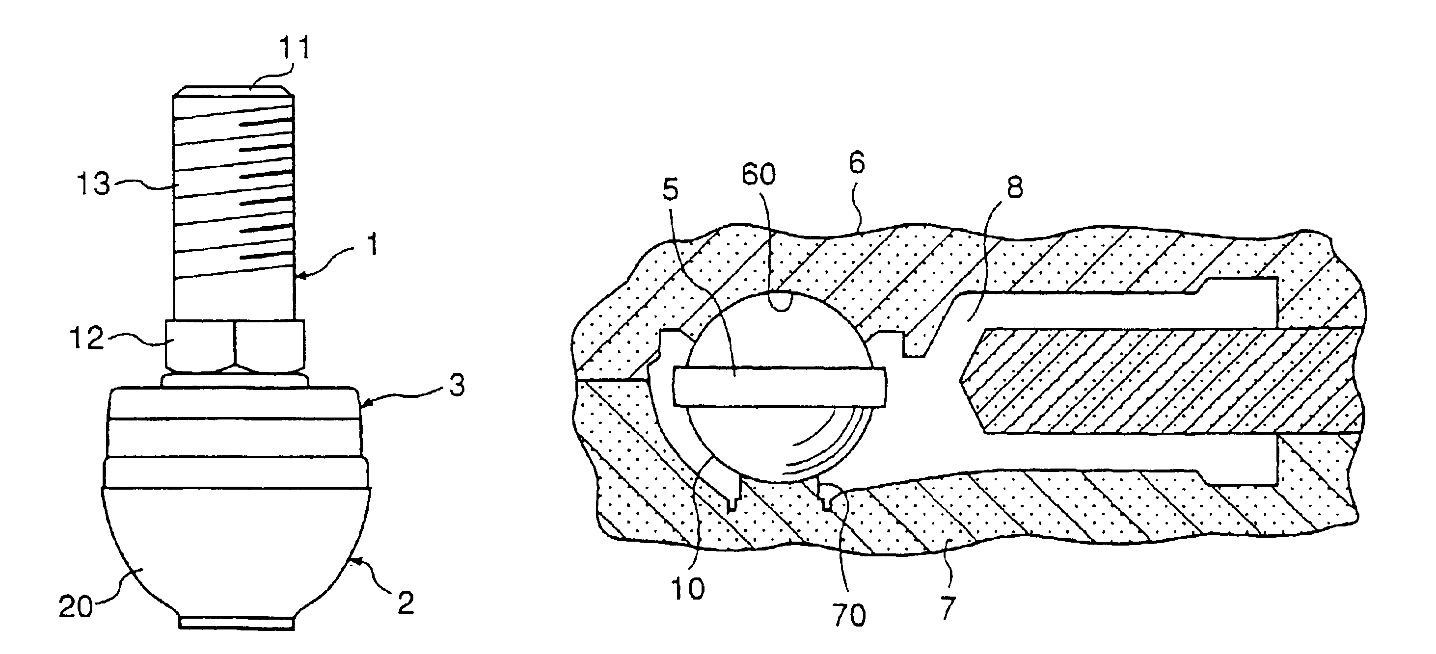
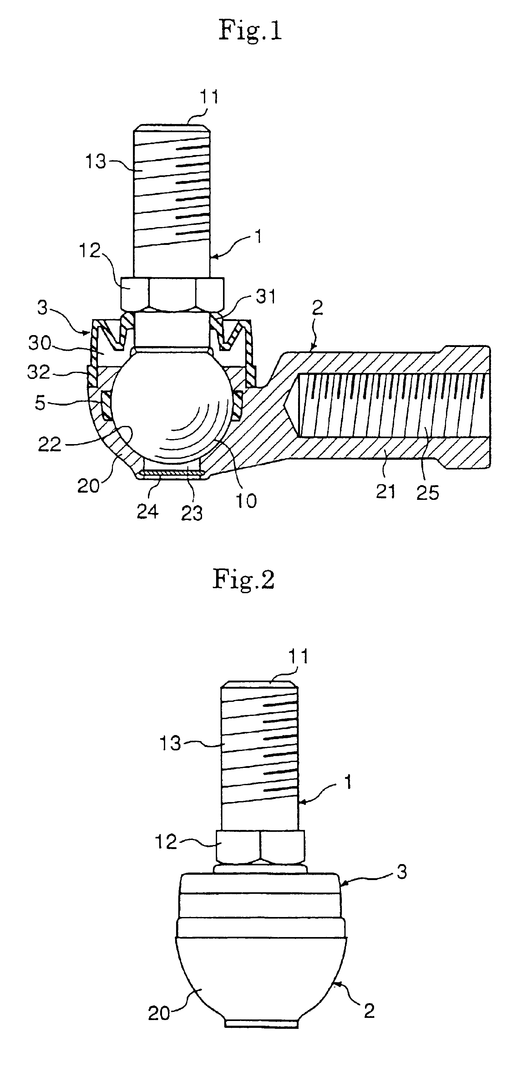
[0032]FIGS. 1 and 2 show a first embodiment of a spherical bearing according to the invention. The spherical bearing is constituted by a ball shank 1 as an inner member having a ball section at an end thereof and a holder 2 as an outer member having a ball bearing section 20 for enclosing and holding the ball section 10 of the ball shank 1, the ball shank 1 and holder 2 being swingably or rotatably coupled.

[0033]The ball shank 1 is formed by welding a rod-shaped shank 11 to a steel ball having a high sphericity to serve as the ball section 10, and a hexagonal bearing surface 12 is formed at the base of the shank 11 for fixing an object to be mounted such as a link. A male thread 13 is formed at the end of the shank 11, and a nut may be engaged with the male thread 13 to sandwich and fix an object to be mounted betwee...


PUM

PropertyMeasurementUnit
temperatureaaaaaaaaaa
sphericityaaaaaaaaaa

Abstract

There are provided a spherical bearing and a method for manufacturing the same, in which both of a ball bearing section and a ball section made of metal can make light and smooth swinging and rotary motions for a long period of time without biased wear and seize-up of those members even if the solid bodies of them can contact with each other due to a discontinuous oil film under a heavy load. A resin liner that contacts the ball section of the inner member in a sliding relationship is embedded in the ball bearing section, and a resin sliding contact surface provided by the resin liner and the metal sliding surface are adjacent to each other without any gap to form a sliding contact surface at the bearing section.

Description

[0001]This is a divisional of application Ser. No. 09 / 841,076 filed Apr. 25, 2001, now abandoned. The disclosure of the prior application is hereby incorporated by reference herein in entirety.FIELD OF THE INVENTION AND RELATED ART STATEMENT[0002]The present invention relates to a spherical bearing in which an inner member having a ball section serving as a center of swinging of a link mechanism and an outer member enclosing and holding the same are swingably or rotatably coupled and which is primarily used as a link motion mechanism or the like in a suspension arm section and a steering section of an automobile or a blade driving section of a combine, and the invention also relates to a method for manufacturing the same.[0003]In general, known spherical bearings of this type include bearings which are equipped with an inner member having a ball section and an outer member having a ball bearing section for enclosing and holding the ball section of the inner member to be coupled to t...

Claims


Application Information

Patent Timeline
Patent Type & Authority Patents(United States)
IPC IPC(8): F16C11/06
CPCF16C11/0633F16C11/0671Y10T29/49648Y10T29/49657Y10T29/49659Y10T29/49655Y10T29/4965Y10T29/49643F16C11/0685F16C2220/02F16C2240/46F16C2208/20
Inventor MICHIOKA, HIDEKAZUKUWABARA, JUNICHITAKAHASHI, KUNIHISAMURATA, TOMOZUMISAKAE, TAKASHITERAMACHI, MITSUHIROYAMAMOTO, TSUYOSHIMORITA, FUMIAKI
Owner THK CO LTD
Why Eureka
Try Eureka