Liquid chromatograph mass spectrometer
a liquid chromatograph and mass spectrometer technology, applied in the direction of filtration separation, separation processes, instruments, etc., can solve the problems of reducing the detection sensitivity, affecting the ionization efficiency, and inconvenient electrolyte solution into the mass spectrometer, so as to achieve quick detection without reducing the separation performance of each separation column and detection sensitivity
- Summary
- Abstract
- Description
- Claims
- Application Information
AI Technical Summary
Benefits of technology
Problems solved by technology
Method used
Image
Examples
first embodiment
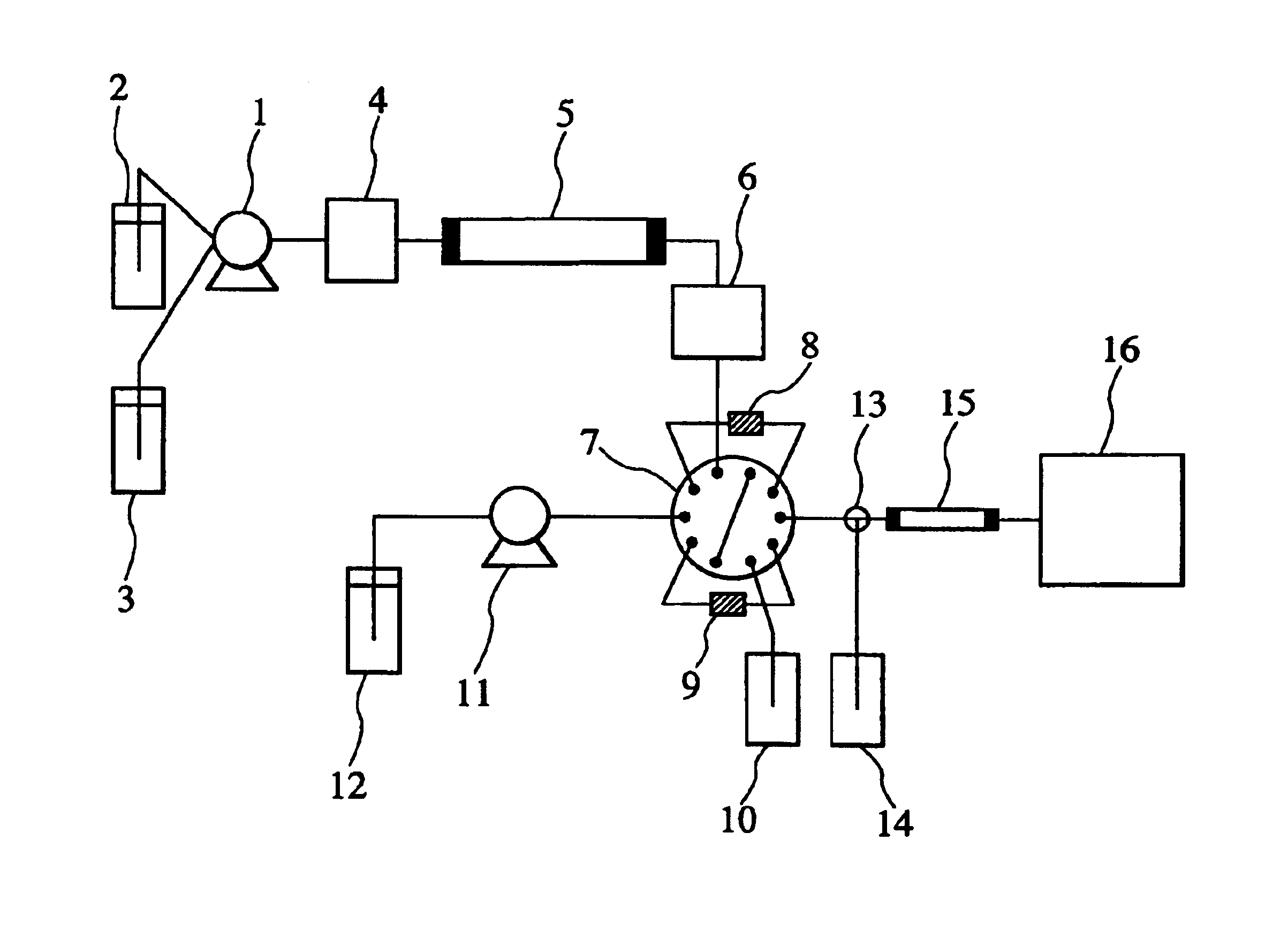
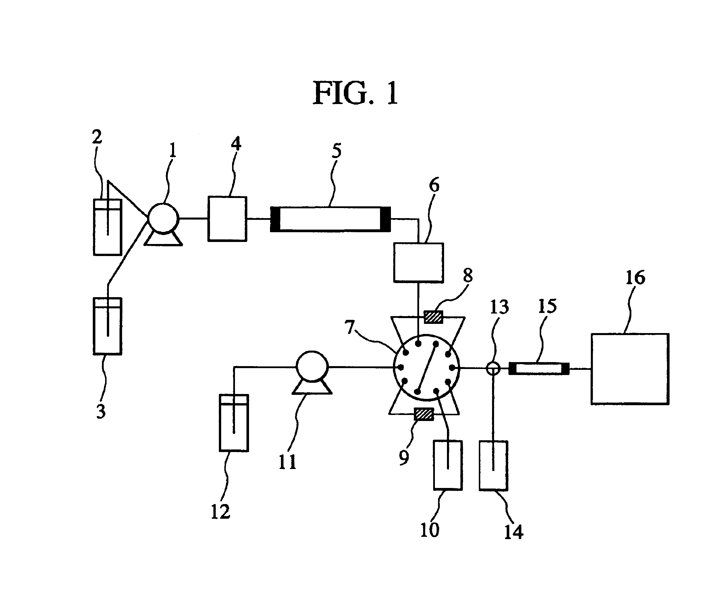
[0036]FIG. 1 is a schematic diagram showing the configuration of a liquid chromatograph mass spectrometer according to a first embodiment of the present invention.
[0037]Referring to FIG. 1, a pump 1 supplies eluents 2 and 3 to a sample injector 4 at a constant flow rate while changing their composition ratio. The sample injector 4 injects a sample into the flow path together with the eluents supplied from the pump 1.
[0038]The components contained in the injected sample are fed to a separation column 5 and eluted in the order of increasing interaction with the separation column 5. Each component eluted from the separation column 5 is detected by an ultraviolet-visible absorbance detector 6 and then introduced to a 10-port switching valve 7.
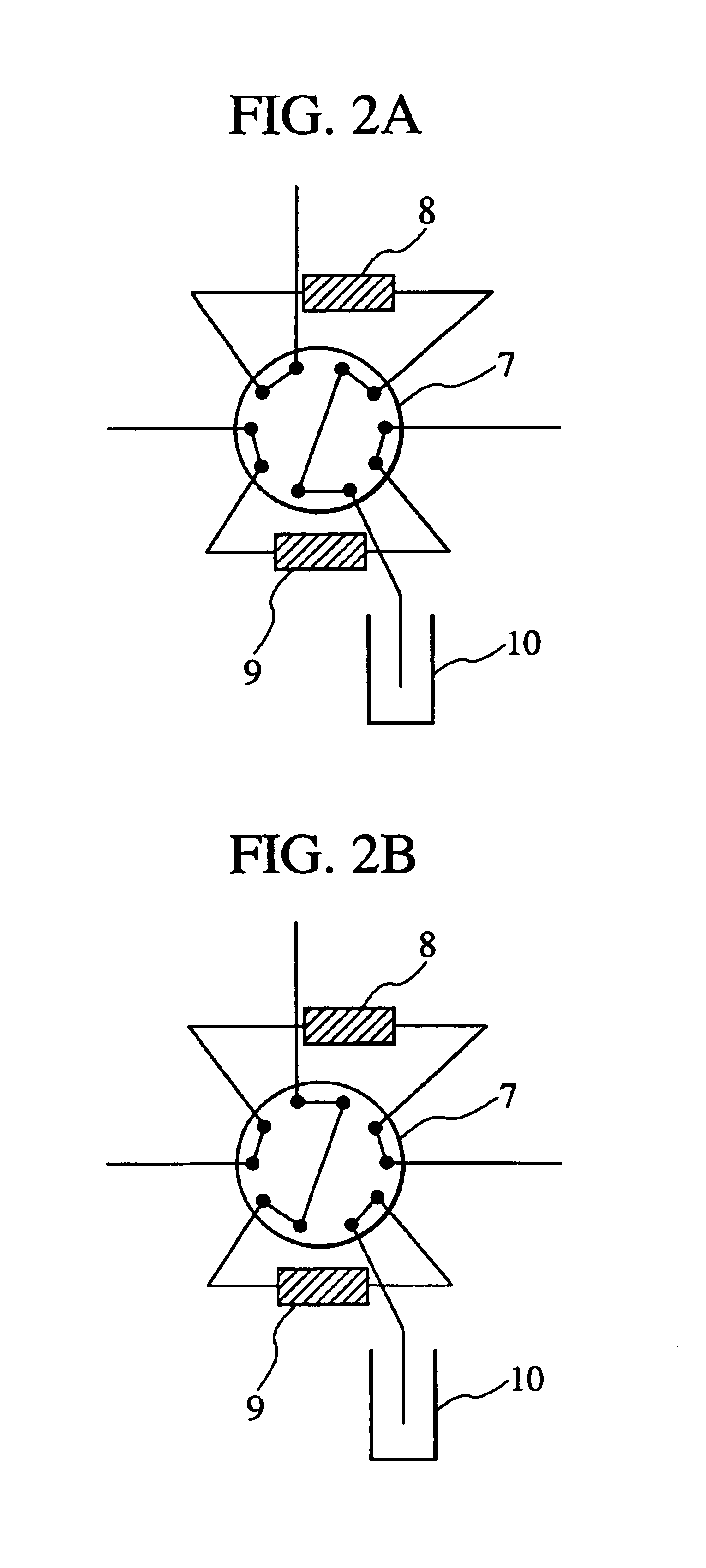
[0039]The 10-port switching valve 7 is connected with two trap columns 8 and 9, and switches the flow paths such that the components eluted from the separation column 5 are supplied to the trap column 8 and the trap column 9 alternately at regular ...
second embodiment
[0072]FIG. 5 is a schematic diagram showing the configuration of a liquid chromatograph mass spectrometer according to a second embodiment of the present invention. The second embodiment is different from the first embodiment in that the second embodiment employs high-speed separation columns 17 and 18 instead of the trap columns 8 and 9 and has omitted the separation column 15. The other components are same as those of the first embodiment.
[0073]Referring to FIG. 5, the 10-port switching valve 7 switches the flow paths at regular time intervals so as to feed each component to either the high-speed separation column 17 or 18. FIG. 6 (including FIGS. 6A and 6B) shows the flow paths formed by the 10-port switching valve 7.
[0074]The 10-port switching valve 7 can switch between two flow path formations, as shown in FIGS. 6A and 6B. When the flow paths shown in FIG. 6A are formed by the 10-port switching valve 7, the components which have passed through the ultraviolet-visible absorbance...
PUM
| Property | Measurement | Unit |
|---|---|---|
| Speed | aaaaa | aaaaa |
Abstract
Description
Claims
Application Information
 - R&D
- Intellectual Property
- Life Sciences
- Materials
- Tech Scout
- Unparalleled Data Quality
- Higher Quality Content
- 60% Fewer Hallucinations
Browse by: Latest US Patents, China's latest patents, Technical Efficacy Thesaurus, Application Domain, Technology Topic, Popular Technical Reports.
© 2025 PatSnap. All rights reserved.Legal|Privacy policy|Modern Slavery Act Transparency Statement|Sitemap|About US| Contact US: help@patsnap.com


