
Display screen and method of manufacture therefor

a technology of display screen and screen body, which is applied in the field of display screen, can solve the problems of limiting the useful resolution of the display, thin screen elements, and becoming obtrusive, and achieve the effect of reducing or eliminating the screen sensitivity to the location of the projector

Inactive Publication Date: 2005-09-13
HONEYWELL INT INC
View PDF34 Cites 24 Cited by
  • Summary
  • Abstract
  • Description
  • Claims
  • Application Information

AI Technical Summary

Benefits of technology

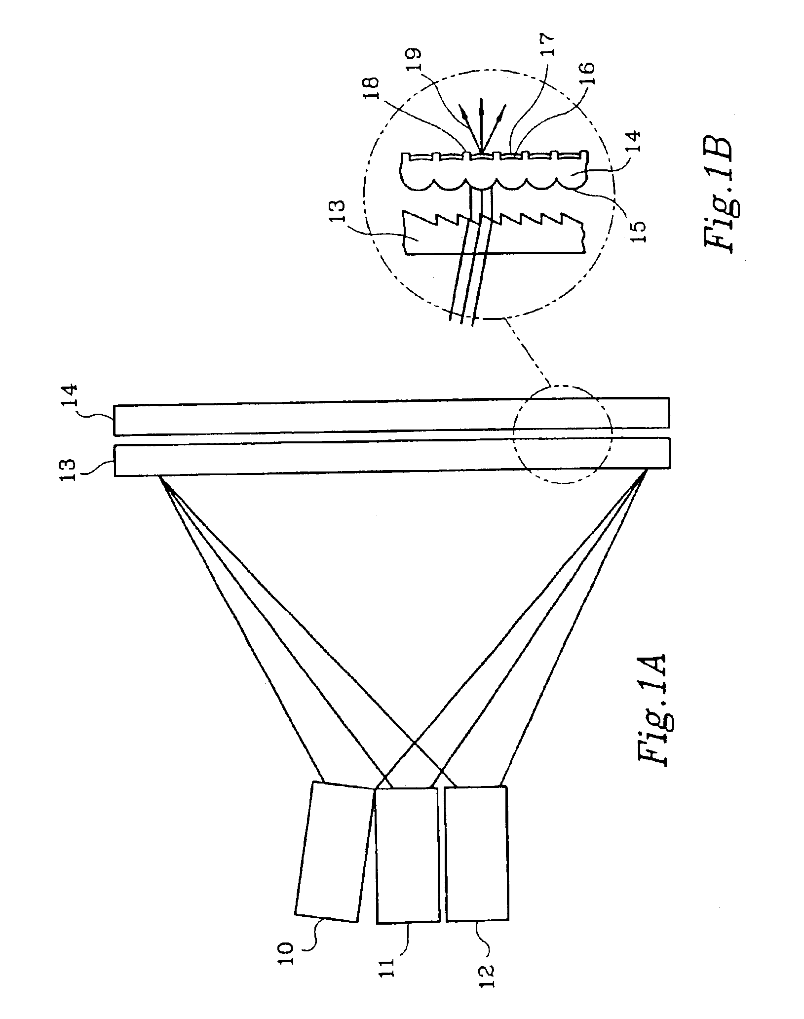
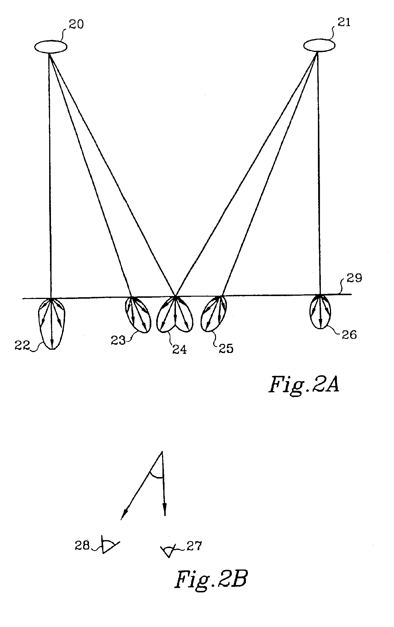
[0014]The present invention overcomes many of the disadvantages of the prior art by providing an angle re-distributing prescreen that minimizes or eliminates the screen sensitivity to projector location, in conjunction with a screen preferably having established screen characteristics such as diffusion characteristics. Compatible screen structures are contemplated, along with methods for fabricating the prescreen and maintaining the desired relationship between the prescreen and the screen.
[0015]The use of an angle re-distributing prescreen to act as a position-independent field lens combined with a separate screen provides a number of advantages over the prior art. For example, the angle re-distributing nature of the prescreen can de-couple the characteristics related to projector location from other screen characteristics. This allows the screen characteristics to be selected on the basis of ambient light performance, light distribution, or other performance considerations important in the target application. Furthermore, when the prescreen is used with a conventional screen such as a conventional diffusion screen, the cost of the screen assembly may be reduced, and the scalability of the screen may be improved.
[0017]To secure the lenticular lens array to the diffusion screen, an edge clamping assembly may be provided. The edge clamping assembly may clamp the edges of the diffusion screen to the lenticular lens array. To maintain a gap between the lenticular lens array and the diffusion screen, one or more edge spacers may be inserted between the lenticular lens array and the diffusion screen. In some embodiments, the edge clamping assembly may apply lateral tension to the lenticular lens array and / or diffusion screen, to provide a more uniform spacing between the lenticular lens array and the diffusion screen.
[0022]As indicated above, the screen assembly of the present invention may be used in conjunction with a tiled projection display. A tiled projection display typically includes two or more projectors, each projecting an image onto a screen. Often, the images of adjacent projectors overlap one another on the incidence side of the screen. The screen assembly of the present invention preferably includes an array of lenslets disposed adjacent to the incidence side of the screen, and a diffusion screen disposed adjacent the emission side of the screen. Configured in this way, the array of lenslets in the prescreen may redirect the incident light from each of the projectors toward the diffusion screen.
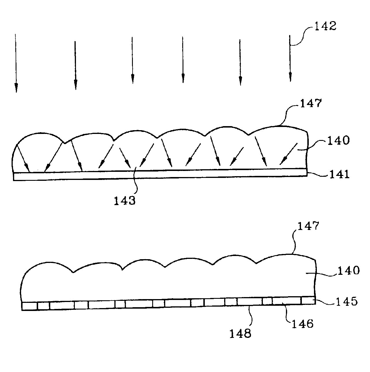
[0023]In some applications, it may be desirable to restrict the spatial extent of the incoming light to a predetermined range for each lenslet. To accomplish this, an array of light apertures are provided. For example, in one illustrative embodiment, an array of lenslets is provided on one side of a substrate, and an array of light apertures is provided on the opposing side of the substrate. The array of apertures are in registration with the array of lenslets. The apertures function to provide an output which is angularly balanced.

Problems solved by technology

At higher resolutions, however, the prior art approaches can become obtrusive and can limit the useful resolution of the display.
U.S. Pat. No. 5,724,188 to Kumagai et al. discusses some of the difficulties in manufacturing suitable screens for high resolution, including difficulties in making thin screen elements, maintaining rigidity and maintaining contrast.
The difficulties associated with prior art screen technologies, both diffusely scattering and lenticular, become increasingly problematic when the resolution is further increased by providing a number of tiled projectors.
Many prior art screens cannot readily support overlap in tiled displays.
The Fresnel lens simply cannot compensate for light emanating from different spaced locations.
This greatly impacts the alignment tolerance and stability of the resulting system.
Further, it may be difficult to mask slight variations in luminance or color coming from adjacent projectors.
Still further constraints are often placed on high resolution systems.
Numerous artifacts such as Moire patterns can result when the screen features interfere with the Fresnel pitch or the projected image pitch.
Pixel substructure may be visible in some or all regions of the screen, luminance efficiency may be of high importance and ambient light conditions may be extreme.
All of these can lead to significant tradeoffs when working within the framework of prior art screen approaches.

Method used


Image

  • Display screen and method of manufacture therefor
  • Display screen and method of manufacture therefor
  • Display screen and method of manufacture therefor

Examples


Embodiment Construction

[0063]The present invention provides an angle re-distributing prescreen that minimizes or eliminates the screen sensitivity to projector location, in conjunction with a screen having established screen characteristics. Compatible screen structures are contemplated, along with methods for fabricating the prescreen and maintaining the desired relationship between the prescreen and the screen.

[0064]FIG. 3 is a schematic diagram showing an illustrative display system 30 in accordance with the present invention. At the core of the system 30 are one or more projection display modules 31. Each display module 31 includes one or more light modulating devices, such as active matrix liquid crystal displays (AMLCDs), digital micromirror devices (DMDs) or similar devices known in the art, as well as drive electronics and a light source. Each display module 31 also includes projection optics which project an image produced at the light modulating device onto the projection screen 35. In one embod...


PUM


Abstract

A screen assembly that combines an angle re-distributing prescreen with a conventional diffusion screen. The prescreen minimizes or eliminates the sensitivity of the screen assembly to projector location. The diffusion screen provides other desirable screen characteristics. Compatible screen structures, along with methods for fabricating high resolution prescreens and methods and devices for maintaining the desired relationship between the prescreen and the diffusion screen are contemplated.

Description

CROSS REFERENCE TO RELATED APPLICATION[0001]This application is a divisional of U.S. patent application Ser. No. 09 / 283,884 filed on Apr. 1, 1999 now U.S. Pat. No. 6,469,830.[0002]The present application is related to U.S. patent application Ser. No. 09 / 283,173, filed Apr. 1, 1999, entitled “DISPLAY SCREEN AND METHOD OF MANUFACTURE THEREFOR”, U.S. patent application Ser. No. 09 / 159,340, filed Sep. 23, 1998, entitled “METHOD AND APPARATUS FOR PROVIDING A SEAMLESS TILED DISPLAY”; U.S. patent application Ser. No. 09 / 159,024, filed Sep. 23, 1998, entitled “METHOD AND APPARATUS FOR CALIBRATING A DISPLAY USING AN ARRAY OF CAMERAS”; and U.S. patent application Ser. No. 09 / 158,995, filed Sep. 23, 1998, entitled “METHOD AND APPARATUS FOR CALIBRATING A TILED DISPLAY”, all of which are assigned to the assignee of the present invention and incorporated herein by reference.BACKGROUND OF THE INVENTION[0003]This invention relates to display screens, and more particularly, to projection. display sc...

Claims


Application Information

Patent Timeline
IPC IPC(8): G03B21/62B65H5/06G02B3/00G02B5/02G03B21/00G03B21/10G03B21/14G03B27/46G03F7/20G03F9/00
CPCG03B21/625
Inventor DUBIN, MATTHEW B.LARSON, BRENT D.
Owner HONEYWELL INT INC
Learn More