Electrical connectors

a technology of electrical connectors and connectors, applied in the direction of electrically conductive connections, coupling device connections, electrical apparatus, etc., can solve the problems of mechanical shock and fatigue, high pressure, abrasion, etc., and achieve the effect of dissipating vibration, flexure and other mechanical forces

Inactive Publication Date: 2005-09-13
DIAMOLD
View PDF5 Cites 21 Cited by
  • Summary
  • Abstract
  • Description
  • Claims
  • Application Information

AI Technical Summary

Benefits of technology

[0051]A key advantage of this form of assembly is that a highly developed electrically and mechanically designed connector will be fitted correctly because the critical operations are performed by the manufacturer and the final assembly, which of necessity must be performed on site, is reduced to a series of simple operations by the use of specially provided jigs and tools. Clearly, critical operations could be performed on site by a skilled person but this relies on him / her being available at the particular time to perform these operations and having the required facilities to hand. As this connector is designed for a critical application, production cannot be jeopardised by the risk of a poorly made connection
[0052]Preferably the mechanical and electrical design incorporates annular upstands surrounding the insulated cores as they enter the insulating member. Between these annular upstands and the insulated cores are channels filled with the mechanically soft, essentially incompressible, electrically insulating substance. The form of these upstands and channels are essentially cylindrical and may be right cylinders, conical cylinders, or any combination of these forms. A further channel may be provided between the insulating member and the crimped portion of core-pin connection. The interactive design of the annular upstands and filled channels provides both an optimal electrical environment to accommodate the passage of electrical current from cable to contact pins as well as an ideal mechanical design to dissipate vibration, flexure and other mechanical forces in the cable which are applied to the connector.

Problems solved by technology

(downhole), thermal shock, high pressures and highly corrosive, abrasive environments.
A further, and frequently major, factor is mechanical shock and fatigue due, particularly, to vibration caused by fluid flow past the connector.
Previous experience with currently available connectors 7 has been unsatisfactory as the factory made units often suffer from problems relating to temperature variations, and the resultant mechanical stresses generated and electrical failure due to movement of the contacts under thermal, or operating pressure, effects.
One particular problem is vibration, induced by the high flow rate of oil and / or gas in liner 4.
High frequency vibrations, even though of only small amplitude, can, over a period of time, have a significantly damaging effect on a cable, e.g. fatigue, chafing of insulation, etc.
The effect of these forces is to weaken the connection both mechanically and electrically and, usually, lead to premature electrical failure, with consequent serious loss of production.
Furthermore, cable 6 is armoured and not easily bent.
Additionally sharp bends place unnecessary stresses in the cable.

Method used


Image

  • Electrical connectors
  • Electrical connectors
  • Electrical connectors

Examples


Embodiment Construction

[0066]In the following description, the same reference numeral is used for identical components or different components fulfilling an identical function.

[0067]The connector A will be described firstly in the assembled condition, to give an overall understanding, and then the method of assembly will be explained in detail.

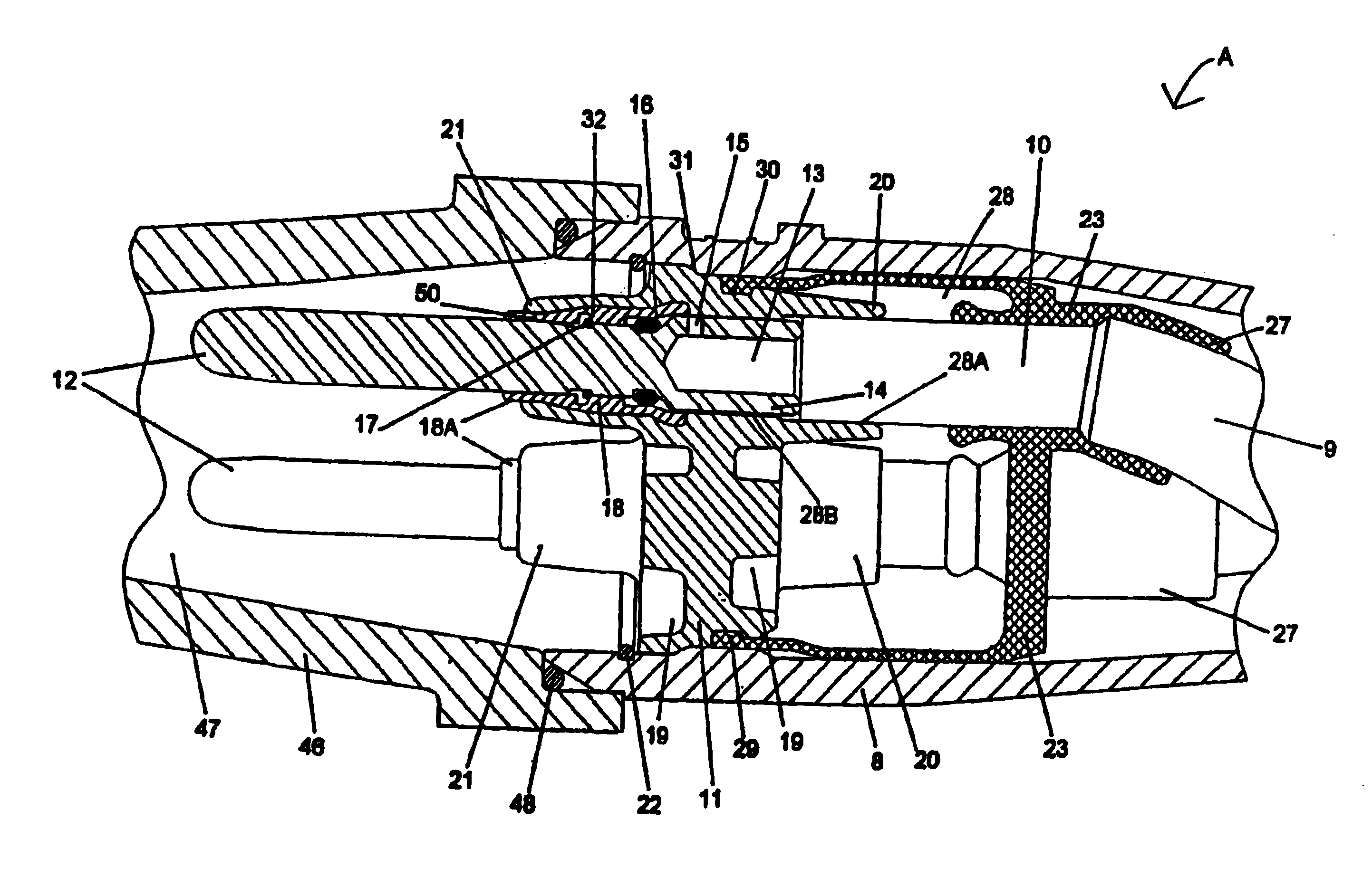
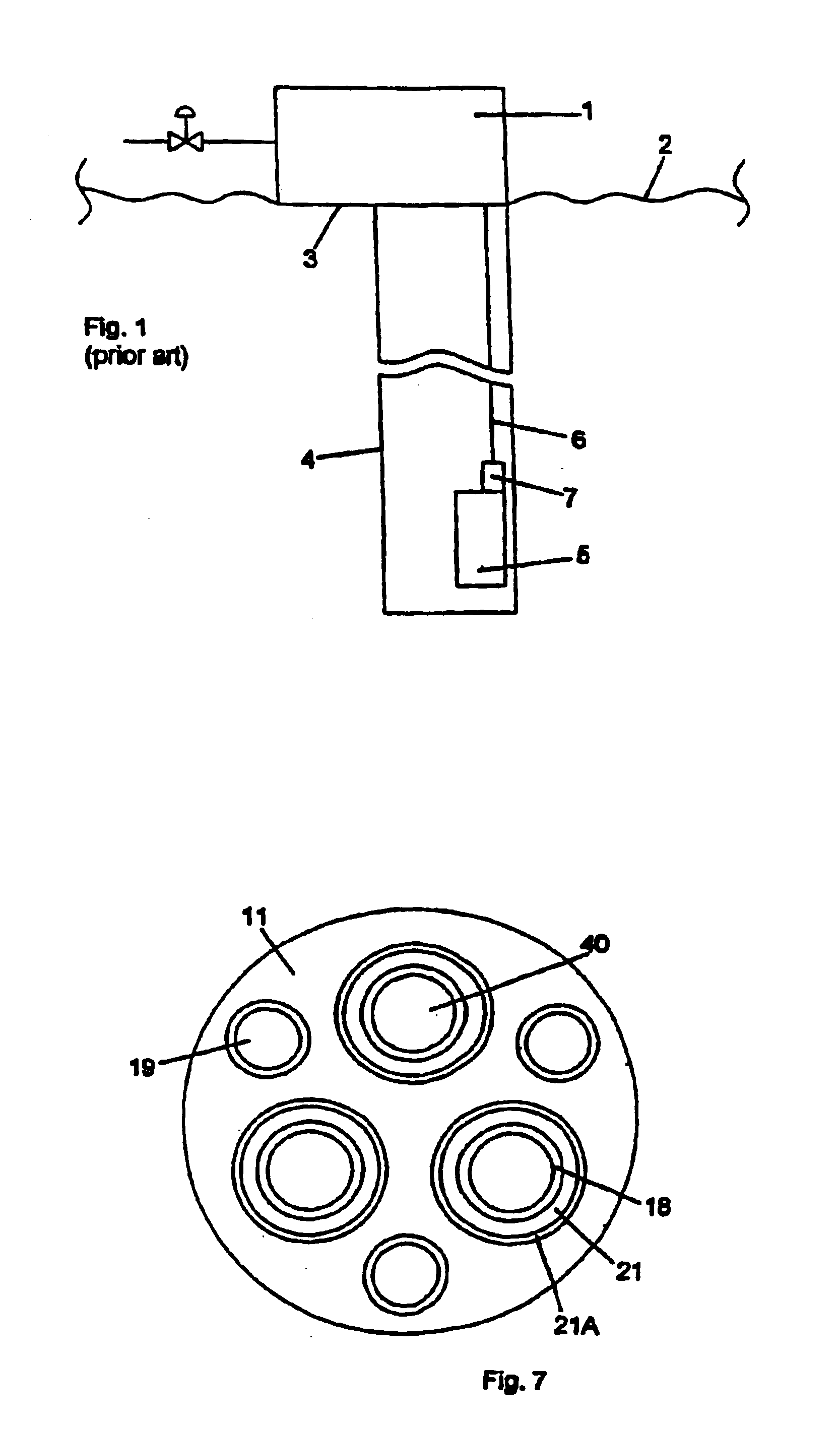
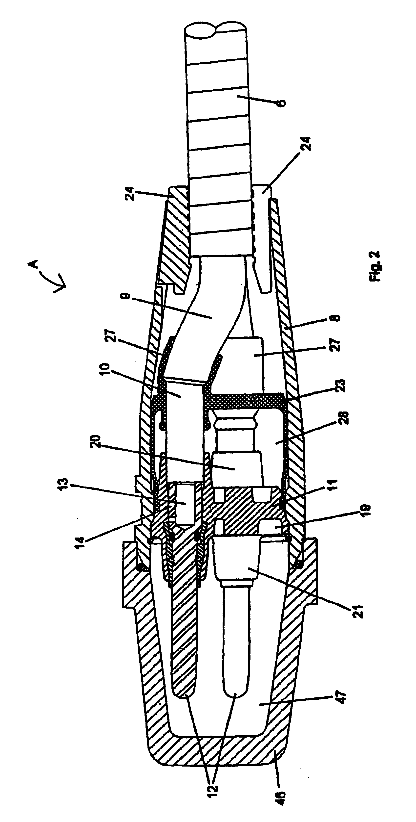
[0068]FIGS. 2 and 5 show armoured cable 6 passing into cable connector A. The particular connector shown has three pins 12 arranged in a triangle to match the socket 7 on ESP 5 (FIG. 1).

[0069]Armoured cable 6 passes through cable clamp 24 into connector housing 8. Beyond clamp 24, the armouring 6 is cut to reveal the lead sheathed conductors 9 which pass through collars 27 in flexible boot 23. Lead sheathing 9 is removed beyond the end of collar 27 to reveal insulation 10. The final section of insulation 10 is removed to reveal core 13 which is crimped in the annular space 14 in the end of contact pin 12. Drilling 15 is provided to view the end of core 13 to ensure ...


PUM


Abstract

An electrical connector and method of making the electrical connection are disclosed for use in particularly arduous conditions, such as down hole oil production applications. The invention provides high electrical integrity with an ability to accommodate steady and/or fluctuating mechanical forces placed via the cable into the connector. Synergy between the mechanical and electrical aspects of the design is taught in which an insulating member, fitted with annular upstands, co-operates with a mechanically soft, essentially incompressible, insulating substance (gel) to cause vibrations in the cable to be dissipated over a length of the insulated cores inside the connector rather that at a single point where it would cause the core to fracture. In addition, annular collars of the gel are provided between the insulating member and the crimped pin-core connections and between the annular upstands and insulated cores to give further cushioning. Because the core insulation sits deep inside the annular upstand of the insulating member and gel collars, this creates a good electrical interface with a long creepage distance. The method covers the creation of the gel collars, alignment of contact pins and insulated cores and assembly of the connector.

Description

BACKGROUND OF THE INVENTION[0001]This specification relates to electrical connectors which have to carry very high powers in compact spaces in hostile environments and covers both the connector design and method of assembling it in the field.[0002]The oil production industry has to contend with some of the most inhospitable conditions anywhere. These include wide temperature variations, e.g. −40° C. (storage of equipment in Alaska) to +120° C. (downhole), thermal shock, high pressures and highly corrosive, abrasive environments. A further, and frequently major, factor is mechanical shock and fatigue due, particularly, to vibration caused by fluid flow past the connector. A typical installation is shown in FIG. 1 where wellhead 1 is shown on seabed 2. Hole liner 4 is suspended from tubing hangar3 and supports a number of items, e.g. electrical submersible pump (ESP) 5, which is powered via protected cable 6. A key item is the motor lead extension (MSE) connector 7, which is sometimes...

Claims


Application Information

Patent Timeline
Patent Type & Authority Patents(United States)
IPC IPC(8): H01R13/533H01R43/00H01R13/52H01R13/523
CPCH01R13/533H01R43/00H01R13/5216H01R13/523
Inventor NICHOLSON, ALLAN
Owner DIAMOLD
Why Eureka
Try Eureka