

Magnetic display device
- Summary
- Abstract
- Description
- Claims
- Application Information
AI Technical Summary
Benefits of technology
Problems solved by technology
Method used
Image

Examples
example 1
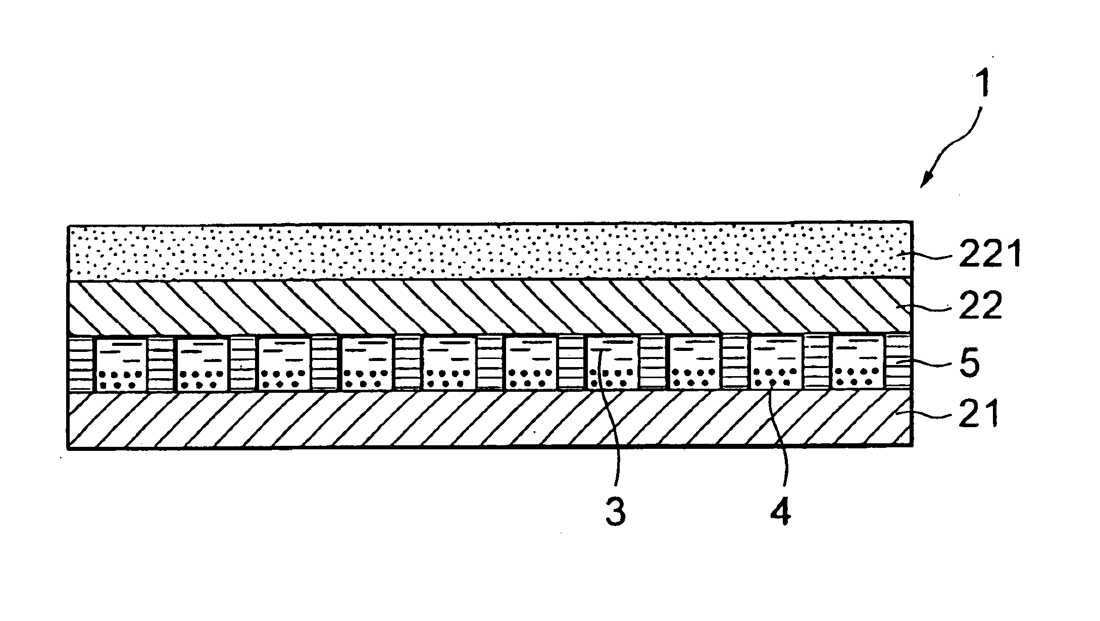
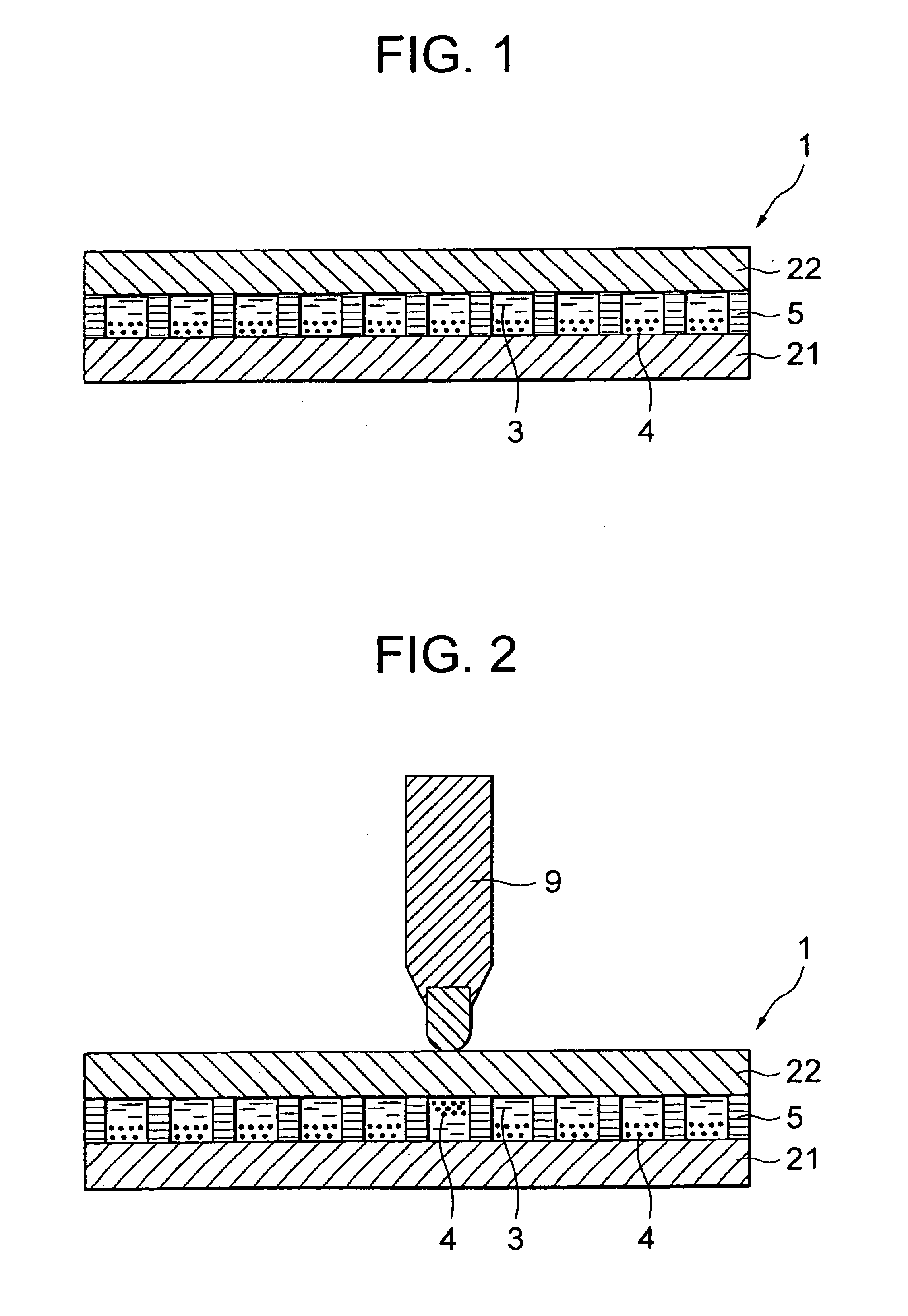
(See FIGS. 1 and 2)
[0084]To a 0.3 mm thick polyvinyl chloride resin sheet a lower flat-sheet display member 21, a top-to-bottom open 1.3 mm thick multi-cellular board 5 having honeycomb-shaped (side length: 4 mm) closed cells (cell wall thickness: 0.05 mm) was bonded with an ethylene-vinyl acetate type emulsion adhesive. Into the cells, a disperse fluid was poured which was prepared by dispersing 9 parts of porous black iron oxide as magnetic particles 4 uniformly in 100 parts of a white dispersion medium obtained by mixing 100 parts of an isoparaffin solvent, 1 part of titanium oxide and 0.1 part of a nonionic surface-active agent thoroughly. Thereafter, using an epoxy resin, an upper flat-sheet display member 22 molded by calender-molding a uniform mixture of 100 parts of vinyl chloride resin, 3 parts of an epoxy resin type plasticizer and 10 parts of an iridescent luster pigment (trade name: IRIODINE 205; available from Merk & Co., Inc.) was laminated. Thus, a magnetic display de...
example 2
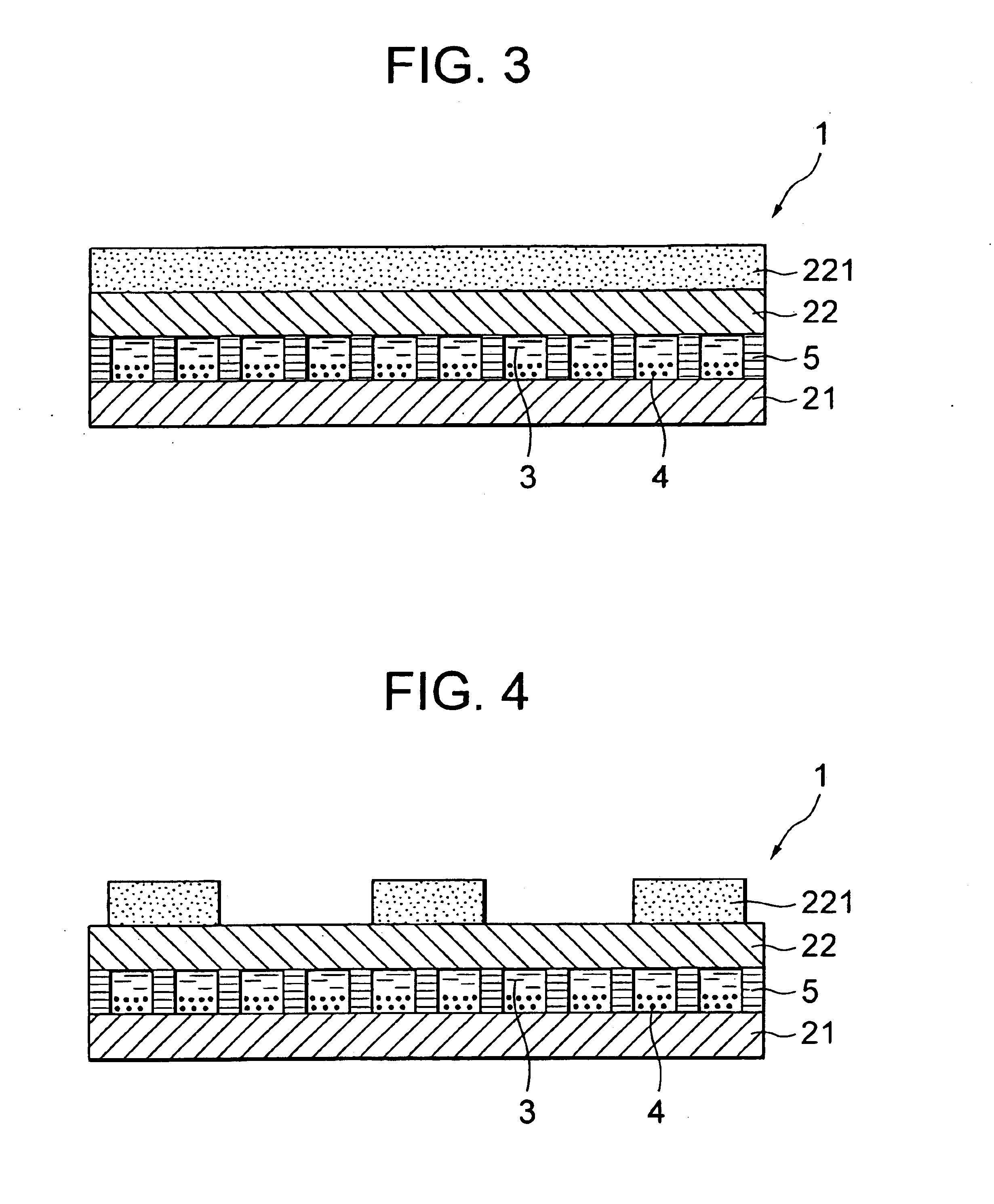
(See FIG. 3)
[0088]To a 300 μm thick polyvinyl chloride film as a lower flat-sheet display member 21, a top-to-bottom open 1.3 mm thick multi-cellular board 5 having honeycomb-shaped (side length: 4 mm) closed cells (cell wall thickness: 0.05 mm) was bonded with an ethylene-vinyl acetate type emulsion adhesive. Into the cells, a disperse fluid was poured which was prepared by dispersing 9 parts of porous black iron oxide as magnetic particles 4 uniformly in 100 parts of the same white dispersion medium as that in Example 1. Thereafter, using an epoxy resin, a polyvinyl chloride film as an upper flat-sheet display member 22 was laminated. Thus, a magnetic display device 1 was obtained.
[0089]On the top surface of the upper flat-sheet display member 22, an ink prepared by dispersing and mixing 5 parts of an iridescent luster pigment (trade name: IRIODINE 221; available from Merk & Co., Inc.), 15 parts of a vinyl chloride-vinyl acetate copolymer resin, 35 parts of xylene, 39 parts of eth...
example 3
(See FIG. 4)
[0093]To a 200 μm thick polyvinyl chloride film as a lower flat-sheet display member 21, a top-to-bottom open 1.3 mm thick multi-cellular board 5 having honeycomb-shaped (side length: 4 mm) closed cells (cell wall thickness: 0.05 mm) was bonded with an ethylene-vinyl acetate type emulsion adhesive. Into the cells, a disperse fluid was poured which was prepared by dispersing 9 parts of porous black iron oxide as magnetic particles 4 uniformly in 100 parts of the same white dispersion medium as that in Example 1. Thereafter, using an epoxy resin, a polyvinyl chloride film as an upper flat-sheet display member 22 was laminated. Thus, a magnetic display device 1 was obtained.
[0094]On the top surface of the upper flat-sheet display member 22, an ink prepared by dispersing and mixing 5 parts of an iridescent luster pigment (trade name: IRIODINE 100; available from Merk & Co., Inc.), 15 parts of a vinyl chloride-vinyl acetate copolymer resin, 35 parts of xylene, 39 parts of eth...
PUM
 Abstract
Description
Claims
Application Information