

Method and apparatus for managing quality of service in network devices
- Summary
- Abstract
- Description
- Claims
- Application Information
AI Technical Summary
Benefits of technology
Problems solved by technology
Method used
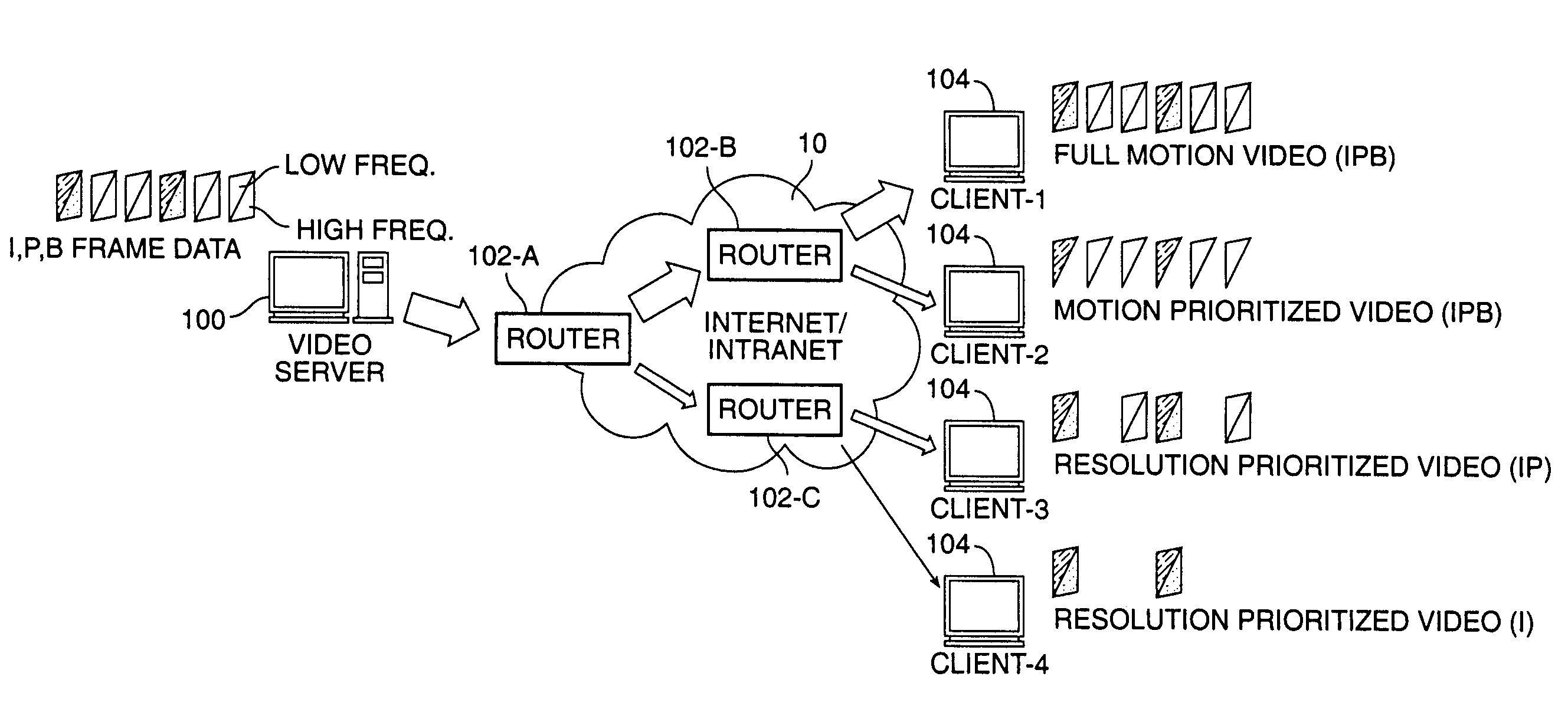
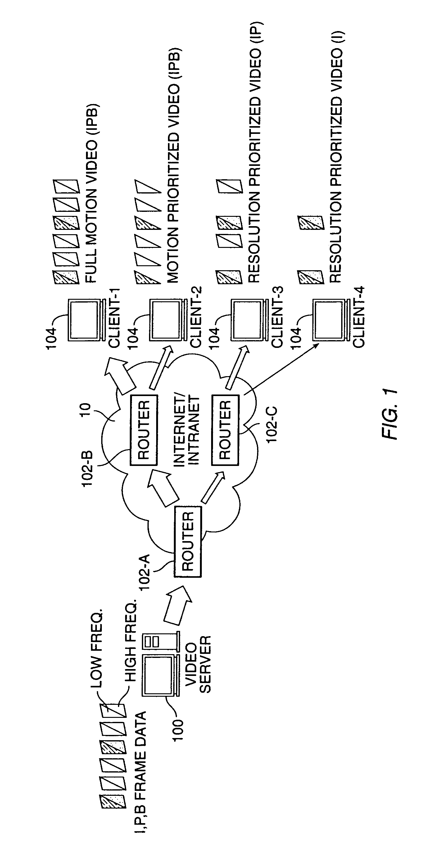
Image

Examples
first embodiment
[0043]Referring to FIGS. 2–4, packet handling in a router 102 in accordance with the invention is shown. FIG. 3 illustrates an embodiment of a flow control table 227. The flow control table includes entries 1, 2, 3, . . . N. Each entry comprises a FLOW field 310, an ACTION field 320, a FLAG field 330, and a NEW—ACTION field 340. The FLOW field 310 further comprises a source address sub-field 312 and a corresponding destination address sub-field 314. Typically, a flow can be identified by[0044]{SRC—ADDR, DST—ADDR, SRC—PORT, DST—PORT, PROTOCOL}.
[0045]The ports are software entities assigned by the protocol (e.g., TCP / IP, UDP / IP, etc.), used to differentiate multiple flows between the same couple of computers (server & client). The FLOW field is matched against the information contained in the header field of an incoming packet, identifying which flow the incoming packet belongs to. The ACTION and NEW—ACTION fields contain QoS parameters which determine the output QoS for an outgoing d...
second embodiment
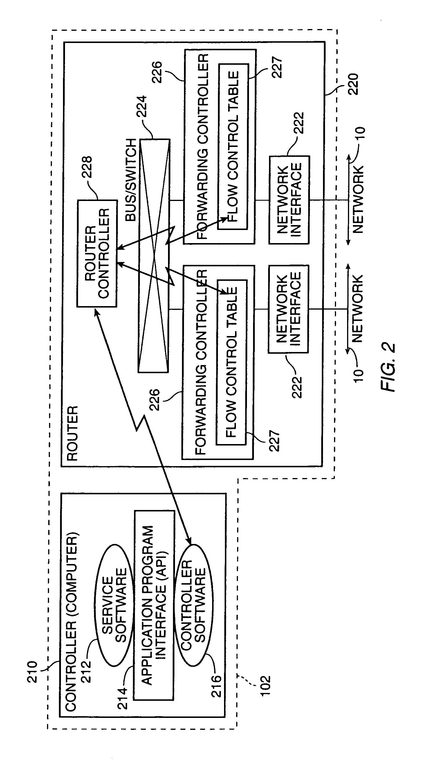
[0068]Referring to FIGS. 2, 7, and 8, packet handling in a router 102 in accordance with the invention is shown. FIG. 7 illustrates another embodiment of flow control table 227, having fields similar to the flow control table illustrated in FIG. 3. The flow control table shown in FIG. 7 includes entries 1, 2, 3, . . . N. Each entry comprises a FLOW field 710, an ACTION field 720, a MASK field 730, and a NEW—ACTION field 740. The FLOW field 710 further comprises a source address sub-field 712 and a corresponding destination address sub-field 714. The ACTION and NEW—ACTION fields contain QoS parameters which determine the output QoS for an outgoing data packet, as will be explained below. The MASK field is a bit pattern.
[0069]FIG. 8 outlines the processing of forwarding controller 226. Processing begins by the arrival of a data packet over network 10 via network interface 222. The forwarding controller inspects the contents of the data packet to find a matching entry in flow control t...
third embodiment
[0086]FIG. 13 shows yet the invention wherein the flow control table 227 incorporates a vector of plural entries of QoS parameters. In addition to the FLOW field 1310 and the ACTION field 1320, a NEW—ACTION—LIST field 1350 is provided. The NEW—ACTION—LIST field 1350 is a pointer to an array of QoS settings 1370. Each entry in the array comprises a MASK field 1330, and a NEW—ACTION field 1340 containing the QoS parameters. Thus, for a given entry in the flow control table 227, there can be a multitude of QoS settings for the corresponding output queue. The particular QoS level chosen depends on the which MASK field 1330 matches the bit pattern contained in the predetermined location of the received data packet.
[0087]The API for setting this variation of the flow control table can be readily obtained by making appropriate modifications to the embodiments of API's illustrated in FIGS. 10–12. The MASK and ACTION data structures would be altered to be lists instead of single element stru...
PUM
 Abstract
Description
Claims
Application Information