Method and apparatus for avoiding unwanted sensing in a cardiac rhythm management device

a rhythm management and heart rhythm technology, applied in the direction of heart stimulators, electrotherapy, therapy, etc., can solve the problems of complex pacing modes and configurations, ineffective stimulation pulses, and inability to achieve the effect of avoiding misidentification of artifacts, reducing the likelihood of failure, and enhancing the blanking or refractory period

Inactive Publication Date: 2005-09-13
CARDIAC PACEMAKERS INC
View PDF8 Cites 14 Cited by
  • Summary
  • Abstract
  • Description
  • Claims
  • Application Information

AI Technical Summary

Benefits of technology

[0014]In use, the cardiac rhythm management device of the present invention may be utilized to stimulate pre-selected chambers of a patient's heart in accordance with a predefined stimulation sequence. The present invention provides a method for assisting a physician in avoiding an unwanted potential by first identifying the unwanted potential by observing all of the cardiac signals sensed from different sites in the heart and then ascertaining a temporal relationship between the unwanted potential and a known, repeatable intrinsic or paced event. The device is then programmed with the known repeatable intrinsic or paced event employed as a trigger event that triggers a blanking or refractory period. A sensing channel where the unwanted potential is identified is then programmed as the channel to which the blanking or refractory period is to be applied. Further, a delay value is programmed that starts with the trigger event and that extends to a point in time before which the unwanted potential is believed not to occur. Finally, a duration of the blanking or refractory period that starts with the end of the delay and extends to cover a period of time during which the unwanted potential is believed to have occurred is programmed.
[0015]It is accordingly a principal object of the present invention to provide an enhanced blanking or refractory period that reduces the likelihood of failure to identify intrinsic events.
[0016]Another object of the present invention is to provide a rhythm management device having a sensing protocol that avoids misidentification of artifacts and evoked potentials while enhancing the ability of the device to sense intrinsic events by increasing the time period for normal sensing.
[0017]Still another object of the present invention is to provide a cardiac rhythm management device that increases the ability of the device to detect tachyarrhythmias.
[0018]Yet another object of the present invention is to provide a cardiac rhythm management device that may include separate refractory and floating refractory periods for each selected cardiac cycle which may be utilized to increase the time period for normal sensing.

Problems solved by technology

The delivery of the stimulation pulse must be delivered at a proper time during the cardiac cycle or the stimulation pulse may not be effective, may not be as effective, or may be undesirable.
As pacemakers have evolved, the pacing modes and configurations have become more intricate and complex, generating an increasing array of polarization voltages and after potentials.
For example, when pacing in the ventricles and sensing in the atrium, an atrial channel of a sensing circuit of the present day cardiac rhythm management devices may have to be refractory most of the time because of a long retrograde conduction time.
Consequently, a P-wave resulting from intrinsic depolarization may easily fall into a refractory or blanking period, in which case the intrinsic atrial events will not be detected by the device.
This reduces the effectiveness of the stimulation protocol of the device.
However, the Routh et al patent does not teach or suggest a method for accounting for the complex polarization voltages and after potentials generated by multiple site pacing.
The number of such blanking or refractory periods will grow exponentially with the number of pacing / sensing sites in a multiple site pacing system, eventually to a point that requires a system size that cannot be accommodated by an implantable device and, moreover, this causes significant difficulties and potential for confusion to the physician programming the implantable device.

Method used


Image

  • Method and apparatus for avoiding unwanted sensing in a cardiac rhythm management device
  • Method and apparatus for avoiding unwanted sensing in a cardiac rhythm management device
  • Method and apparatus for avoiding unwanted sensing in a cardiac rhythm management device

Examples


Embodiment Construction

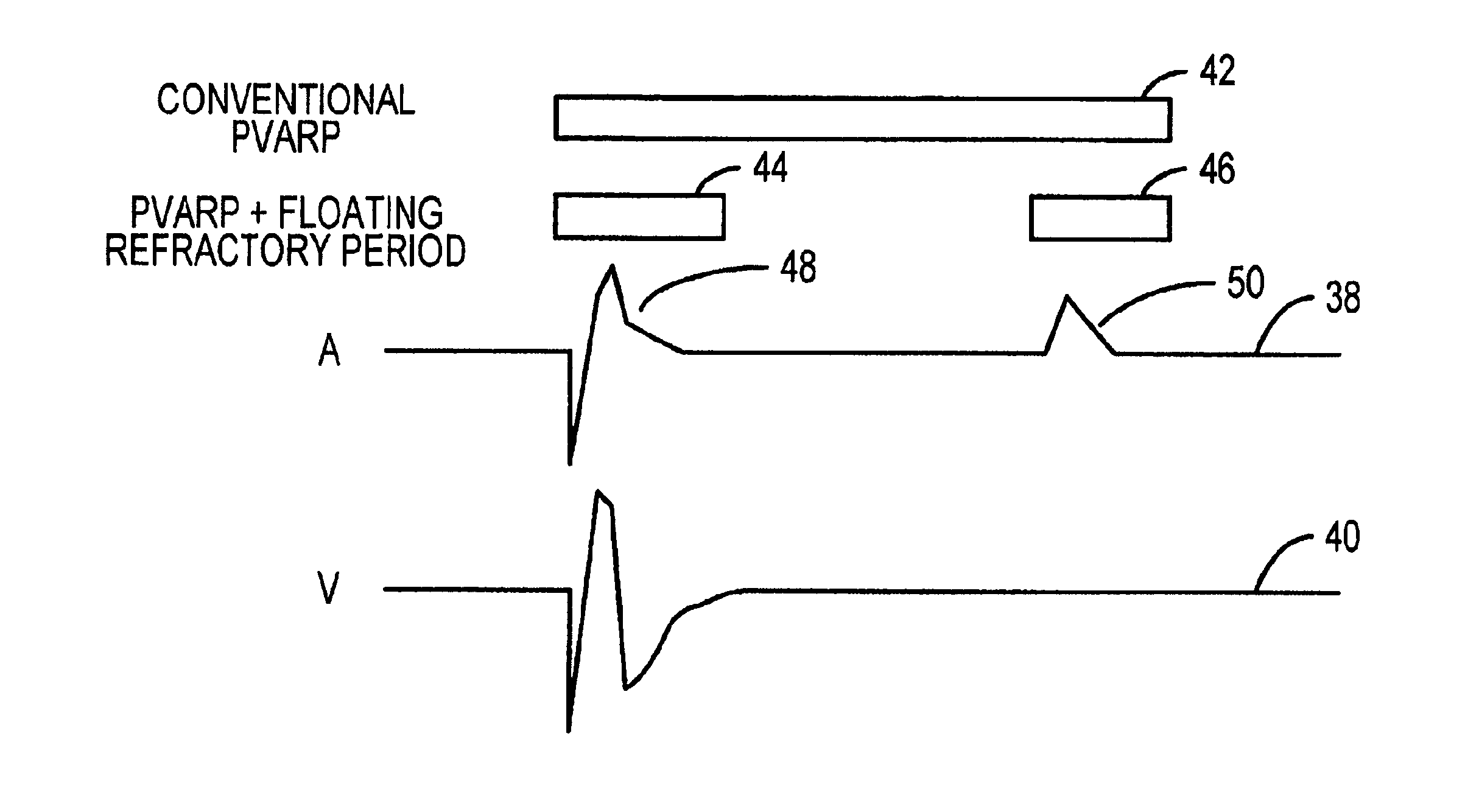
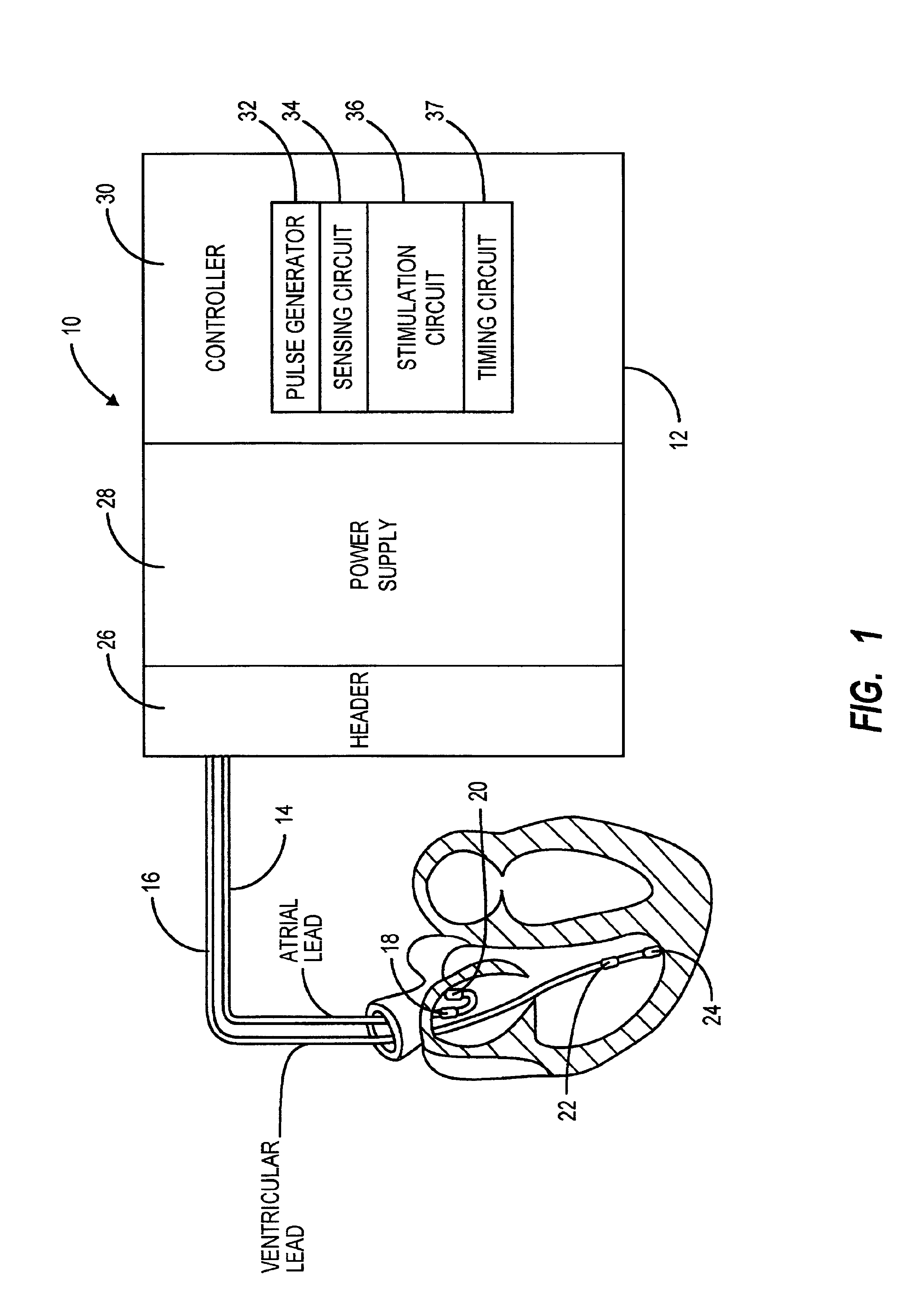
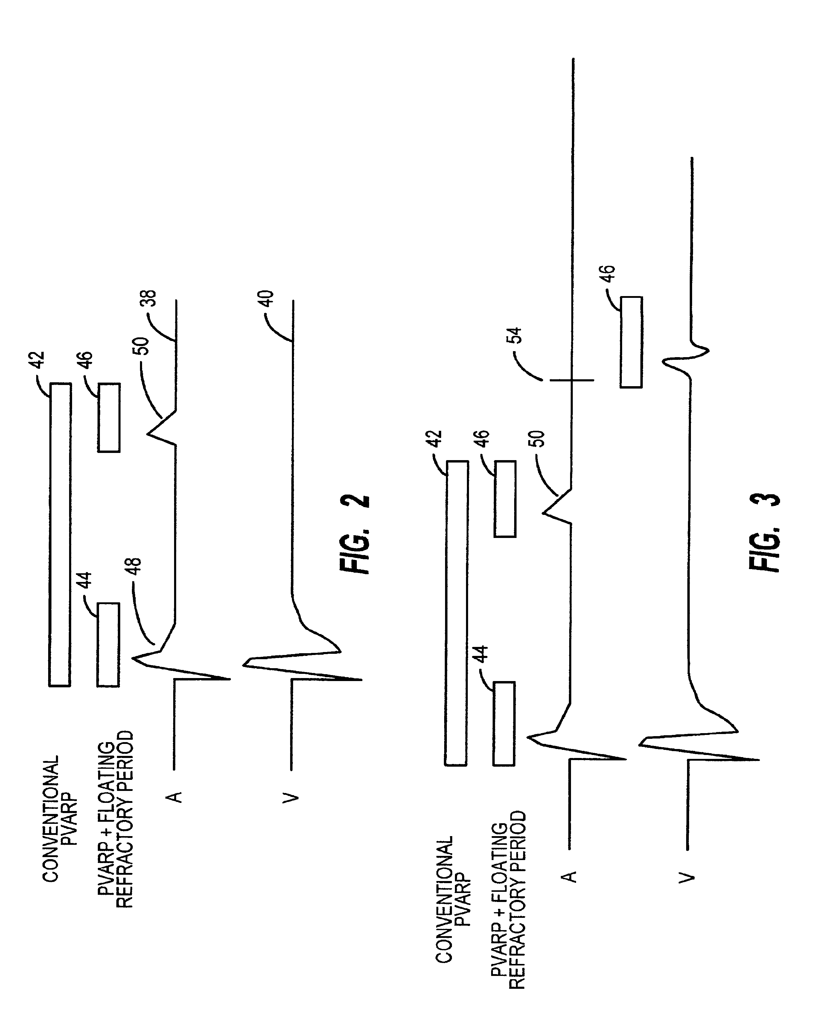
[0026]The present invention represents broadly applicable improvements to the sensing protocol of a cardiac rhythm management device. The embodiments detailed herein are intended to be taken as representative or exemplary of those in which the improvements of the invention may be incorporated and are not intended to be limiting. Referring first to FIG. 1, the cardiac rhythm management device 10 of the present invention is shown including a housing 12, atrial lead 14, and ventricular lead 16. The distal end of the atrial lead shown positioned in the right atrium includes electrodes 18 and 20. The distal end of the ventricular lead 16 shown positioned in the right ventricle includes ventricular electrodes 22 and 24. The atrial lead 14 and ventricular lead 16 are engaged to header 26 affixed to the housing and may be electrically coupled to the power supply 28 and controller 30 contained within the housing 12 in a known fashion. It should be appreciated that other lead configurations o...


PUM


Abstract

A cardiac rhythm management device that utilizes blanking or refractory periods to avoid misidentification of artifacts and evoked potentials, wherein the refractory periods are discontinuous and may be dependent upon sensed events, expiration of a predefined timing interval, or stimulation events in the same or other chambers of the heart. The discontinuous refractory periods enhance the ability of the device to sense intrinsic events. The present invention includes separate refractory and floating refractory periods incorporated within the sensing protocol for each selected cycle, thereby increasing the time period for normal sensing.

Description

BACKGROUND OF THE INVENTION[0001]I. Field of the Invention[0002]This invention relates generally to a cardiac rhythm management device suitable for delivering stimulation pulses to a patient's heart and more particularly relates to a cardiac rhythm management device that utilizes a sensing protocol which avoids misidentification of artifacts and evoked potentials enhancing the ability of the device to sense intrinsic events.[0003]II. Discussion of the Prior Art[0004]Over the years, cardiac rhythm management devices have been utilized for supplanting some or all of an abnormal heart's natural pacing functions. These devices have remedied abnormalities including total or partial heart block, arrhythmias, congestive heart failure, congestive heart disorders and other various rhythm disturbances within the heart. Typically, the rhythm management device includes a power supply and pulse generator for generating electrical stimulus pulses delivered to a pre-selected area of the heart. An ...

Claims


Application Information

Patent Timeline
Patent Type & Authority Patents(United States)
IPC IPC(8): A61N1/362A61N1/37
CPCA61N1/3704A61N1/3712
Inventor TANG, ZHENGNIANSPINELLI, JULIO C.STAHMANN, JEFFREY E.WENTKOWSKI, RENE H.KRAMER, ANDREW P.HAEFNER, PAUL A.
Owner CARDIAC PACEMAKERS INC
Why Eureka
Try Eureka