Methods for reducing bitline voltage offsets in memory devices

a memory device and voltage offset technology, applied in the field of integrated circuits, can solve the problems of affecting the speed at which sense amplification may occur, voltage offset that becomes problematic, and the voltage offset is quite insignificant, so as to reduce the physical size of the core cell, eliminate the voltage offset between bitlines, and reduce line capacitance

Inactive Publication Date: 2005-09-13
ARM INC
View PDF62 Cites 11 Cited by
  • Summary
  • Abstract
  • Description
  • Claims
  • Application Information

AI Technical Summary

Benefits of technology

[0017]Broadly speaking, the present invention fills these needs by providing memory layout techniques that substantially eliminate voltage offsets between memory core cell bitlines, as well as techniques for laying out core cells in substantially less semiconductor chip area. It should be appreciated that the present invention can be implemented in numerous ways, including as a process, an apparatus, a system, a device, or a method. Several embodiments of the present invention are described below.
[0021]In still yet a further embodiment, a memory core circuit design is disclosed. The circuit design has a polysilicon design that is routed over a semiconductor substrate. The polysilicon design is configured to define six gates of a core cell, and the core cell has four transistors that define two cross-coupled inverters. The cross-coupled inverters are electrically cross-coupled by a portion of the polysilicon design, a portion of a metallization line that is routed on a first metallization line, and a portion of a metallization line that is routed on a second metallization layer. Wherein the multi-layer electrical cross-coupling substantially reduces a physical size of the core cell.
[0022]Advantageously, the various embodiments of the present invention provide methods and apparatus for substantially eliminating voltage offsets between bitlines, and also provides techniques for designing very compact core cell layouts in multi-level semiconductor devices. As a further advantage, compact core cells have reduced line capacitance, which will necessarily improve performance. Other aspects and advantages of the invention will become apparent from the following detailed description, taken in conjunction with the accompanying drawings, illustrating by way of example the principles of the invention.

Problems solved by technology

Even though such offsets are expected and usual, these voltages offsets are quite insignificant compared to the 500 millivolt voltage differential required for triggering amplification by a sense amplifier.
Unfortunately, voltage offsets in the range of between about 5 and 30 millivolts will necessarily begin to hamper the speed at which sense amplification may occur.
It is this voltage offset that becomes problematic when voltage sensing between the bitlines is required at lower voltage differentials.
Consequently, even very small voltage offsets will have substantially increased performance deteriorating ramifications.
Unfortunately, conventional memory device performance is limited by the expected fabrication imperfections and layout constraints that produce imbalances in capacitive loading of the bitlines of each core cell 12.
Although this layout works well, the space needed to layout the polysilicon lines and complete the cross-coupling in polysilicon have severely limited the ability to reduce a core cell's overall size.
Because six transistor core cells require four transistors (i.e., two N-type transistors and two P-type transistors for the two inverters) in a cross-coupled arrangement, it is very difficult to further shrink the size of a standard core cell 12.

Method used


Image

  • Methods for reducing bitline voltage offsets in memory devices
  • Methods for reducing bitline voltage offsets in memory devices
  • Methods for reducing bitline voltage offsets in memory devices

Examples


Embodiment Construction

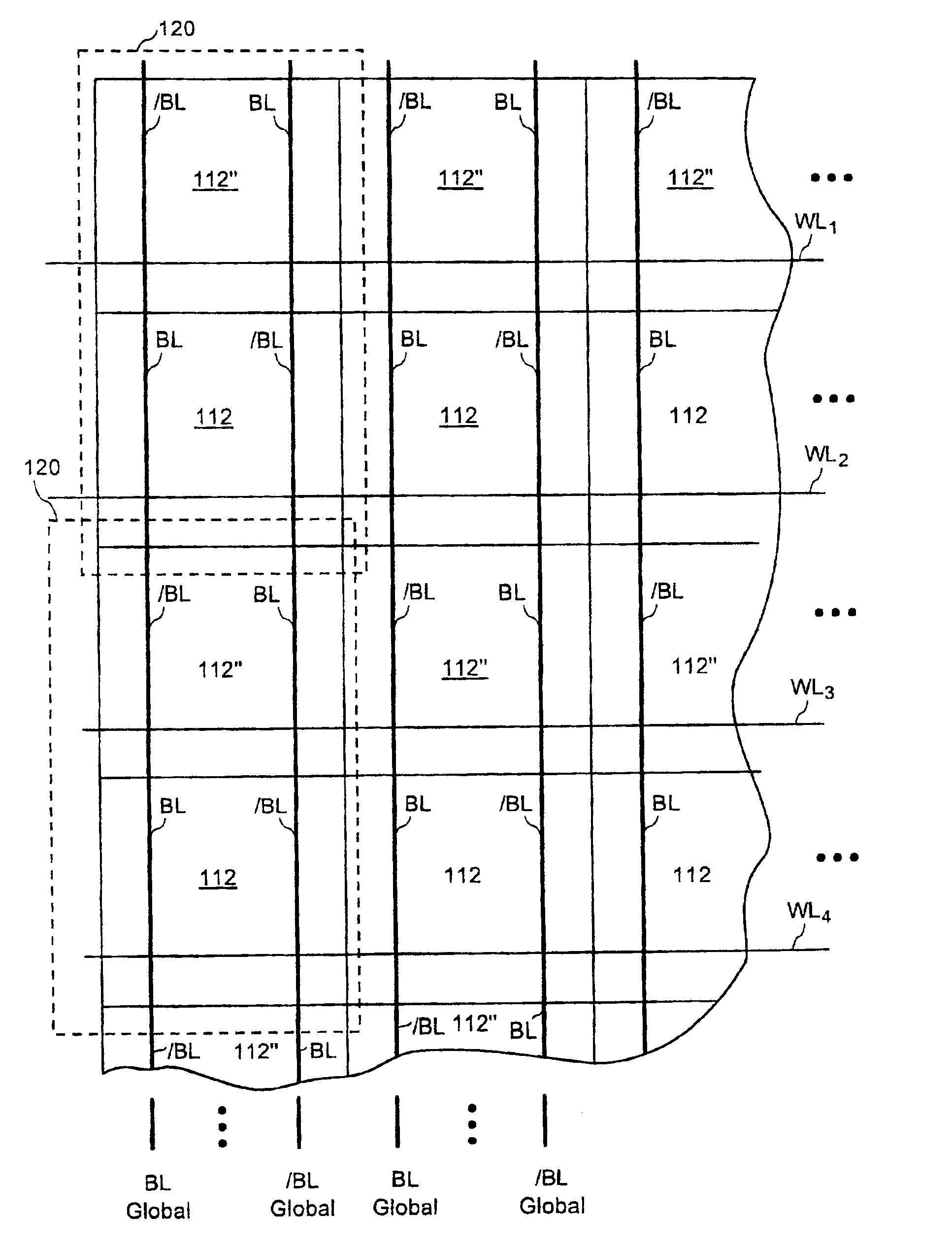
[0035]An invention for memory layout techniques that substantially eliminate voltage offsets between memory core cell bitlines, and techniques for laying out core cells in substantially less semiconductor chip area are disclosed. In the following description, numerous specific details are set forth in order to provide a thorough understanding of the present invention. It will be understood, however, to one skilled in the art, that the present invention may be practiced without some or all of these specific details. In other instances, well known process operations have not been described in detail in order not to unnecessarily obscure the present invention.

[0036]Although several embodiments of the present invention are directed toward asynchronous and synchronous SRAM memory devices, the capacitive load balancing and layout designs of the present invention may also be applicable to other memory devices, such as a ROM device, a RAM device, a DRAM device, an EPROM device, an EEPROM de...


PUM


Abstract

A method of designing a memory device that has substantially reduced bitline voltage offsets is provided. The method includes providing a memory core having a depth that defines a plurality of words, and a word width that is defined by multiple pairs of a global bitline and a global complementary bitline. The method also includes designing a core cell having a bitline and a complementary bitline, and designing a flipped core cell that has a flipped bitline and a flipped complementary bitline. Further, the method includes arranging a core cell followed by a flipped core cell along each of the multiple pairs of the global bitline and the global complementary bitline. Preferably, the bitline of the core cell is coupled with the flipped complementary bitline of the flipped core cell, and the complementary bitline of the core cell is coupled to the flipped bitline of the flipped core cell.

Description

CROSS-REFERENCE TO RELATED APPLICATIONS[0001]This Application is a continuation of pending U.S. application Ser. No. 09 / 442,877, filed Nov. 18, 1999 now U.S. Pat. No. 6,470,304, which is a Divisional Application of Ser. No. 09 / 015,427 filed Jan. 29, 1998, now U.S. Pat. No. 6,016,390, each of which is herein incorporated by reference.BACKGROUND OF THE INVENTION[0002]1. Field of the Invention[0003]The present invention relates generally to integrated circuits, and more particularly to the optimized design and fabrication of memory device core cells.[0004]2. Description of the Related Art[0005]Semiconductor memory cores are typically laid-out in array format, such that each individual core cell is coupled by a wordline and a pair of differential bitlines. To read or write data from or to a selected core cell, associated memory accessing circuitry is commonly designed around a memory core. For example, several key memory access circuit components typically include addressing circuitry f...

Claims


Application Information

Patent Timeline
Patent Type & Authority Patents(United States)
IPC IPC(8): G11C7/00G11C7/18H01L27/11
CPCG11C7/18H01L27/1104H10B10/12
Inventor BECKER, SCOTT T.
Owner ARM INC
Why Eureka
Try Eureka