Method for forming a GMR sensor having improved longitudinal biasing

a technology of longitudinal biasing and read head, which is applied in the field of fabrication of giant magnetoresistive (gmr) read head, can solve the problems of unwanted side reading of lol design, and achieve the effect of high magnetic stability

Inactive Publication Date: 2005-09-20
HEADWAY TECH INC
View PDF9 Cites 31 Cited by
  • Summary
  • Abstract
  • Description
  • Claims
  • Application Information

AI Technical Summary

Benefits of technology

[0012]Accordingly, it is a first object of the present invention to provide a GMR sensor with an ultra-narrow (<0.15 microns) read width and a longitudinally biased free layer having high magnetic stability.

Problems solved by technology

Thus, these edges remain operative to some extent and produce the unwanted side reading of the LOL design.

Method used


Image

  • Method for forming a GMR sensor having improved longitudinal biasing
  • Method for forming a GMR sensor having improved longitudinal biasing
  • Method for forming a GMR sensor having improved longitudinal biasing

Examples


Embodiment Construction

[0027]A preferred embodiment of the present invention provides a GMR read head with a longitudinal biasing structure of improved magnetic stability and a method of forming it.

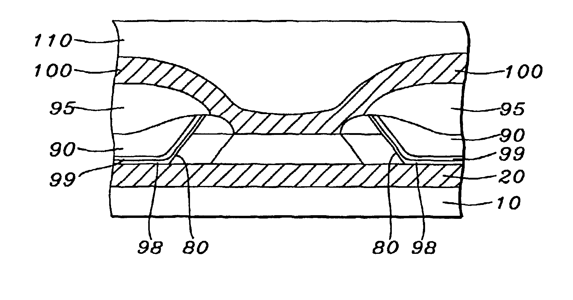
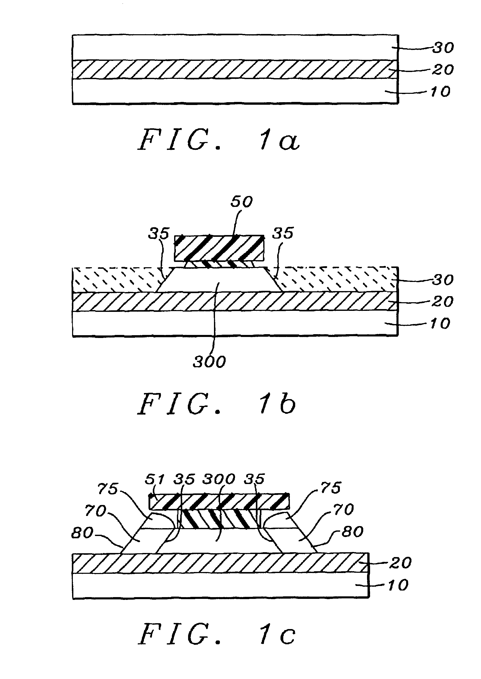
[0028]Referring first to FIG. 1a, there is seen a schematic cross-sectional view of a partially fabricated read head taken through its ABS plane. There is seen a substrate which is a bottom shield layer (10), which may be an upper shield of a magnetic write head formed below the read head. On this substrate is then formed an insulating gap layer (20), which may be a layer of insulating material such as alumina, formed to a thickness between approximately 50 and 300 angstroms. On the gap layer is then formed a GMR structure (30), which is a laminate of layers which, when patterned, will form a GMR sensor element. This element may be any of several types of GMR sensor configurations, including, among others, top or bottom spin valves, all including a ferromagnetic free layer requiring longitudinal biasing.

[0029]R...


PUM

PropertyMeasurementUnit
thicknessaaaaaaaaaa
thicknessaaaaaaaaaa
widthaaaaaaaaaa

Abstract

A GMR sensor having improved longitudinal biasing is provided as is a method of forming it. The improved biasing is provided by longitudinal biasing structures in which a soft magnetic layer is interposed between a hard magnetic biasing layer and the lateral edge of the GMR sensor element. The soft magnetic layer eliminates the need for a seed layer directly between the hard magnetic layer and the GMR element and provides improved coupling to the free layer of the GMR element and a substantial reduction in random domain variations.

Description

BACKGROUND OF THE INVENTION[0001]1Field of the Invention[0002]This invention relates generally to the fabrication of a giant magnetoresistive (GMR) read head and more particularly to the improvement of the longitudinal magnetic bias of such a read head by a novel longitudinal biasing structure that interposes a soft magnetic layer between the GMR sensor element and a permanent magnet biasing layer.[0003]2Description of the Related Art[0004]A giant magnetoresistive (GMR) read head requires longitudinal biasing of its free layer in order to operate in a linear readback region in as noise-free a manner as possible. The longitudinal biasing serves two complementary purposes: 1) it maintains the magnetic moment of the free layer at an optimal position (the bias point) during quiescence, so that rotations of the magnetic moment about that point during readback produce a linear response; 2) it stabilizes the domain structure of the free layer so that noise-producing domain variations (Bark...

Claims


Application Information

Patent Timeline
Patent Type & Authority Patents(United States)
IPC IPC(8): G11B5/39
CPCB82Y10/00B82Y25/00G11B5/3906G11B2005/3996Y10T29/49052Y10T29/49046Y10T29/49044Y10T29/49043Y10T29/49032Y10T29/49039
Inventor GUO, YIMINZHU, LI-YAN
Owner HEADWAY TECH INC
Why Eureka
Try Eureka