Minimal fluid forced convective heat sink for high power computers

a heat sink and low-flow technology, applied in indirect heat exchangers, semiconductor/solid-state device details, lighting and heating apparatus, etc., can solve the problems of large amount of waste heat, high cost of existing working fluid systems, and inability to fully exploit the heat removal capacity of heat sinks, etc., to achieve the effect of enhancing the efficiency of heat sinks

Active Publication Date: 2005-09-20
LENOVO PC INT
View PDF16 Cites 25 Cited by
  • Summary
  • Abstract
  • Description
  • Claims
  • Application Information

AI Technical Summary

Benefits of technology

[0006]In the preferred embodiment a thermally conductive can is between the heat sink and spool. The working fluid flows between the can and spool, with the can being in thermal contact with the heat sink. The can may be thin, wherein most heat from the component is first convected away by the circulating water and then conducted through the can to the heat sink. Or, the can may be relatively thick (e.g., between one half millimeter and two millimeters), wherein heat from the hot component is conducted directly through the can to the portions of the heat sink fins that are near the component, and wherein heat from the hot component is also convected away by the water for conduction through the can to the portions of the heat sink fins that are distanced from the component, thereby enhancing the efficiency of the heat sink.

Problems solved by technology

As personal computers become ever more powerful, they tend to generate larger amounts of waste heat that must be removed at low cost to the manufacturer.
Furthermore, existing working fluid systems typically are expensive, require internal piping, etc.
Still further, existing fan-based systems that blow air across fins underuse the portions of the fins that are furthest away from the component being cooled, thereby failing to fully exploit the heat removal capacity of the heat sink.

Method used


Image

  • Minimal fluid forced convective heat sink for high power computers
  • Minimal fluid forced convective heat sink for high power computers
  • Minimal fluid forced convective heat sink for high power computers

Examples


Embodiment Construction

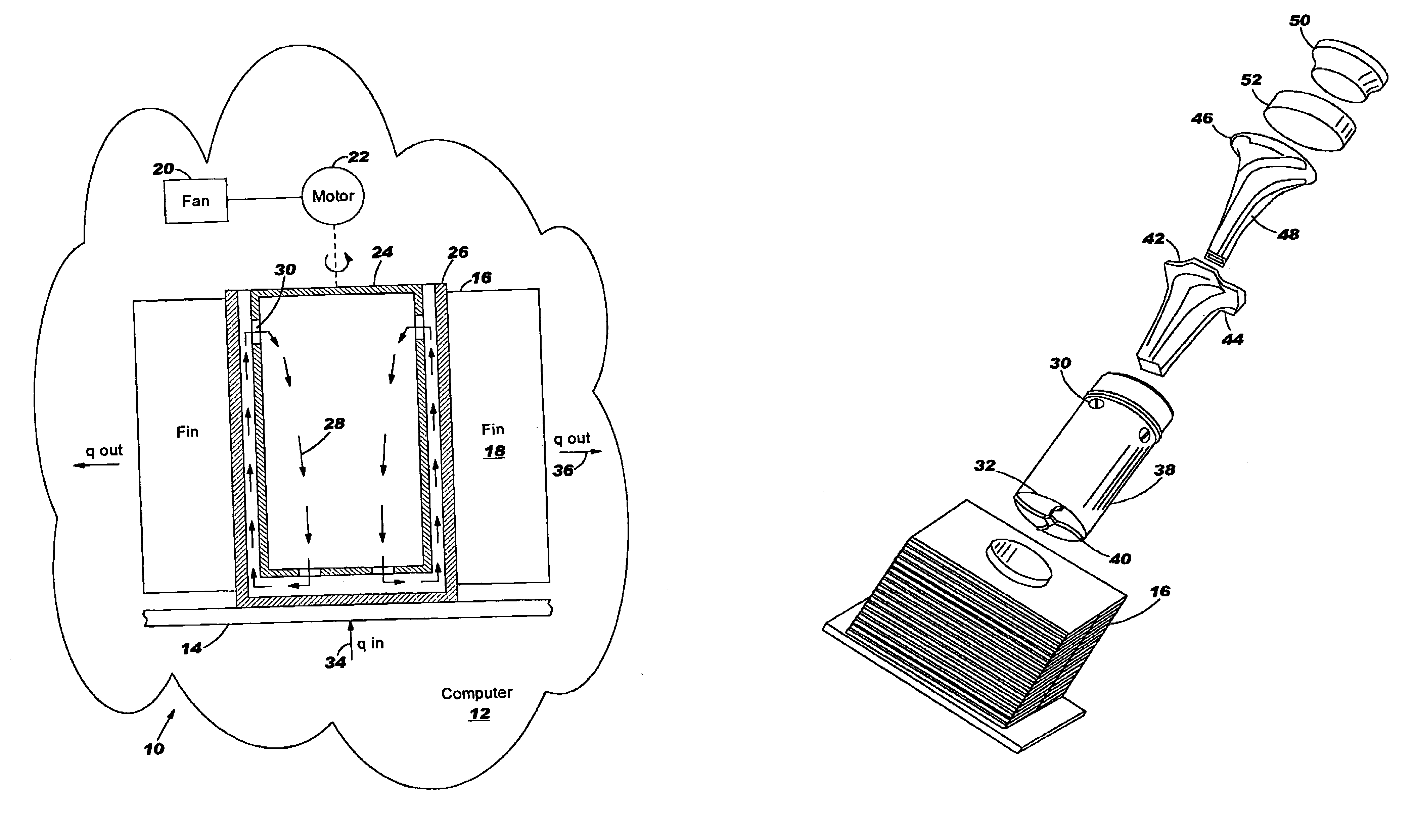
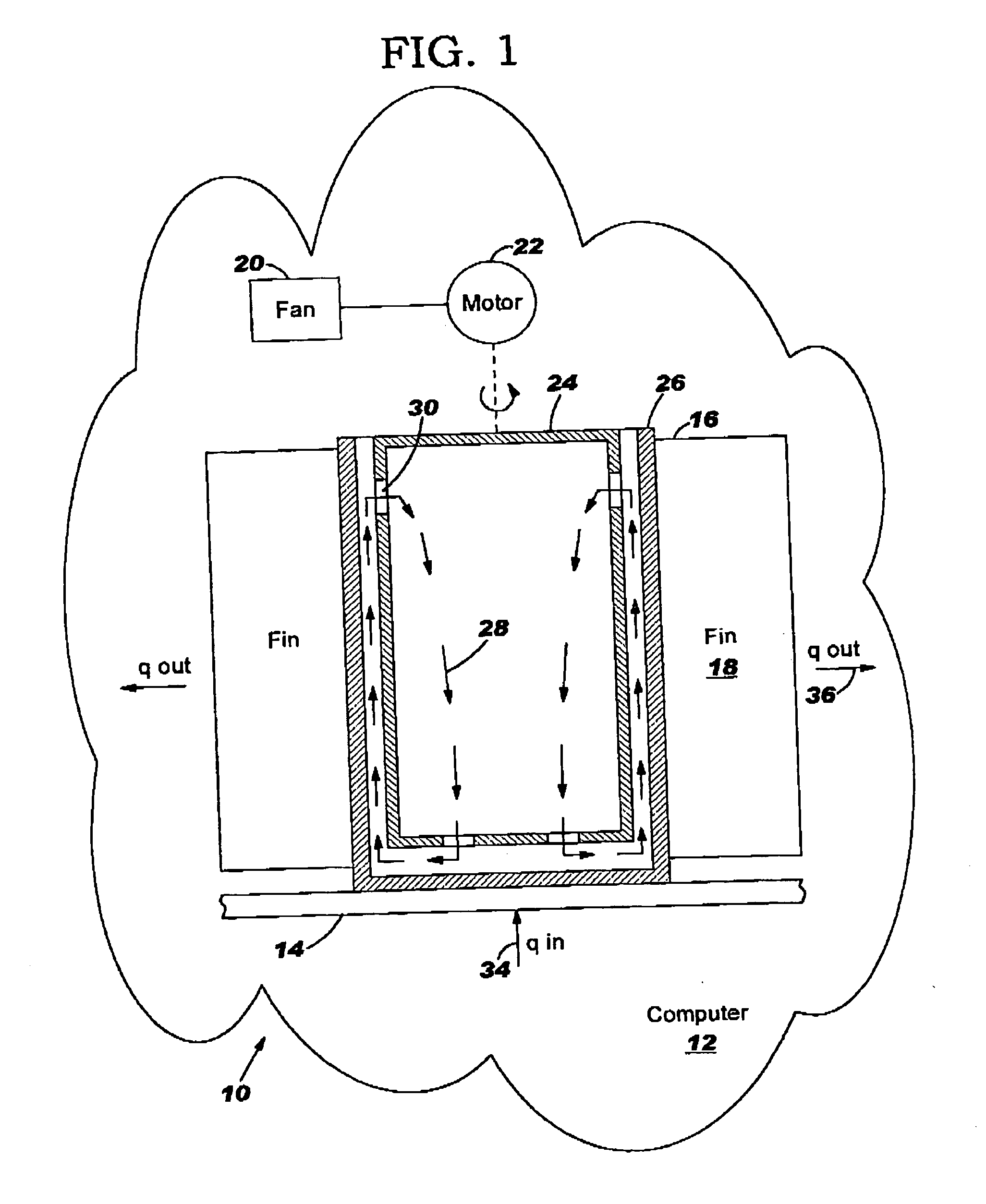
[0013]Referring initially to FIG. 1, a heat removal system is shown and generally designated 10 for a computer 12 that includes a component or components 14 to be cooled, such as a processor chip. As shown, the system 10 includes one or more heat sinks 16 each of which preferably is a fin-type heat sink that has plural thin metal plates, or fins, 18. In the preferred embodiment a fan 20 that is driven by a motor 22 blows air past the fins 18.

[0014]In accordance with the present invention, a spool 24 is rotatably disposed in the heat sink 16. When the heat sink 16 is an axial flow heat sink, the fan 20 and spool 24 may be rotated by a common motor 22, as indicated by the line from the motor 22 to the spool 24 indicating a mechanical or magnetic coupling. On the other hand, when the heat sink 16 is a transverse flow heat sink, the fan 20 and spool 24 are rotated by respective motors. In either case, the motor or motors may be controlled as appropriate by the computer 12 to establish a...


PUM


Abstract

A heat removal system for a computer has a heat sink and a spool rotatably disposed in the heat sink. The spool includes fluid inlets and outlets, and water circulates in a closed loop from the inlets, through the spool, through the outlets, past the computer component to be cooled, and between the heat sink and the spool to transfer heat to the heat sink, then back to the inlets. A thermally conductive can is between the heat sink and spool such that the working fluid flows between the can and spool.

Description

FIELD OF THE INVENTION[0001]The present invention relates generally to heat removal in computers.BACKGROUND OF THE INVENTION[0002]As personal computers become ever more powerful, they tend to generate larger amounts of waste heat that must be removed at low cost to the manufacturer. Currently, most personal computers have heat sinks that conduct heat from components such as the processor of the computer to the air inside the computer chassis, with a fan circulating air across the heat sink.[0003]More heat removal capability might be required than can be provided with a fan. As understood by the present invention, the heat removal capacity of a circulating fluid heat removal device is limited by the viscosity of the working fluid and the thermal resistance between the component sought to be cooled and the air. Furthermore, existing working fluid systems typically are expensive, require internal piping, etc. Still further, existing fan-based systems that blow air across fins underuse ...

Claims


Application Information

Patent Timeline
Patent Type & Authority Patents(United States)
IPC IPC(8): F28F5/00H05K7/20H01L23/473
CPCH01L23/473F28D2015/0291H01L2924/0002H01L2924/00
Inventor FARROW, TIMOTHY SAMUELJUNE, MICHAEL SEANMAKLEY, ALBERT VINCENT
Owner LENOVO PC INT
Why Eureka
Try Eureka