Magnetic recording medium

a recording medium and magnetic technology, applied in the direction of magnetic recording, protective coatings for layers, instruments, etc., can solve the problems of inability to read, frequent reading errors, and inability to accurately detect the position so as to suppress the migration of contaminants and suppress the adhesion and fly stiction effect of the magnetic recording head

Inactive Publication Date: 2005-09-20
WD MEDIA SINGAPORE PTE
View PDF6 Cites 73 Cited by
  • Summary
  • Abstract
  • Description
  • Claims
  • Application Information

AI Technical Summary

Benefits of technology

[0020]It is an object of this invention to provide a magnetic recording medium capable of suppressing migration of contaminants remarkable in a disk drive operated in the LUL system and capable of suppressing adhesion and fly stiction of a magnetic recording head.
[0021]It is another object of this invention to provide a magnetic recording medium prevented from occurrence of fly stiction or other defects even if the flying height of a magnetic recording head is as small as 15 nm or less.
[0022]It is still another object of this invention to provide a technique of improving a production yield of a magnetic recording medium.

Problems solved by technology

With the transition from the CSS system to the LUL system, however, the magnetic recording head suffers corrosion of a read element portion thereof and frequent occurrence of fly stiction during operation at a flying position.
In this event, reading errors frequently occur and, sometimes, a reading operation is completely impossible.
This results in frequent occurrence of irregular variation in output level of the readout signal.
Sometimes, the magnetic recording head at a flying positoin is brought into contact with the magnetic recording medium to cause crash so that the magnetic recording medium is broken.
The fly stiction often occurs suddenly without any sign or precursory condition and is one of defects which are difficult to control.
On the other hand, the above-mentioned cleaning function is not achieved in the LUL system because the magnetic recording head does not slide over the magnetic recording medium in contact therewith.
The inventors have found out that, in the LUL system without the cleaning function, the contaminants migrating to and condensed in the magnetic recording head, particularly, acidic contaminants such as sulfate contaminants, chloride contaminants, and nitride contaminants cause corrosion of the read element portion.
In particular, a magnetoresistive read element (for example, MR, GMR, TMR elements) capable of obtaining a high output level is susceptible to corrosion.
The lubricant of the magnetic recording medium, thus migrating and deposited onto the magnetic recording head, tends to seriously disturb the flying posture of the magnetic recording head, resulting in occurrence of the fly stiction.
If the amount of those deposited substances or contaminants on the magnetic recording head reaches a predetermined level, the deposited substances will fall down onto the magnetic recording medium to cause crash while the magnetic recording head is operated at a flying position.

Method used


Image

  • Magnetic recording medium
  • Magnetic recording medium

Examples


example 1

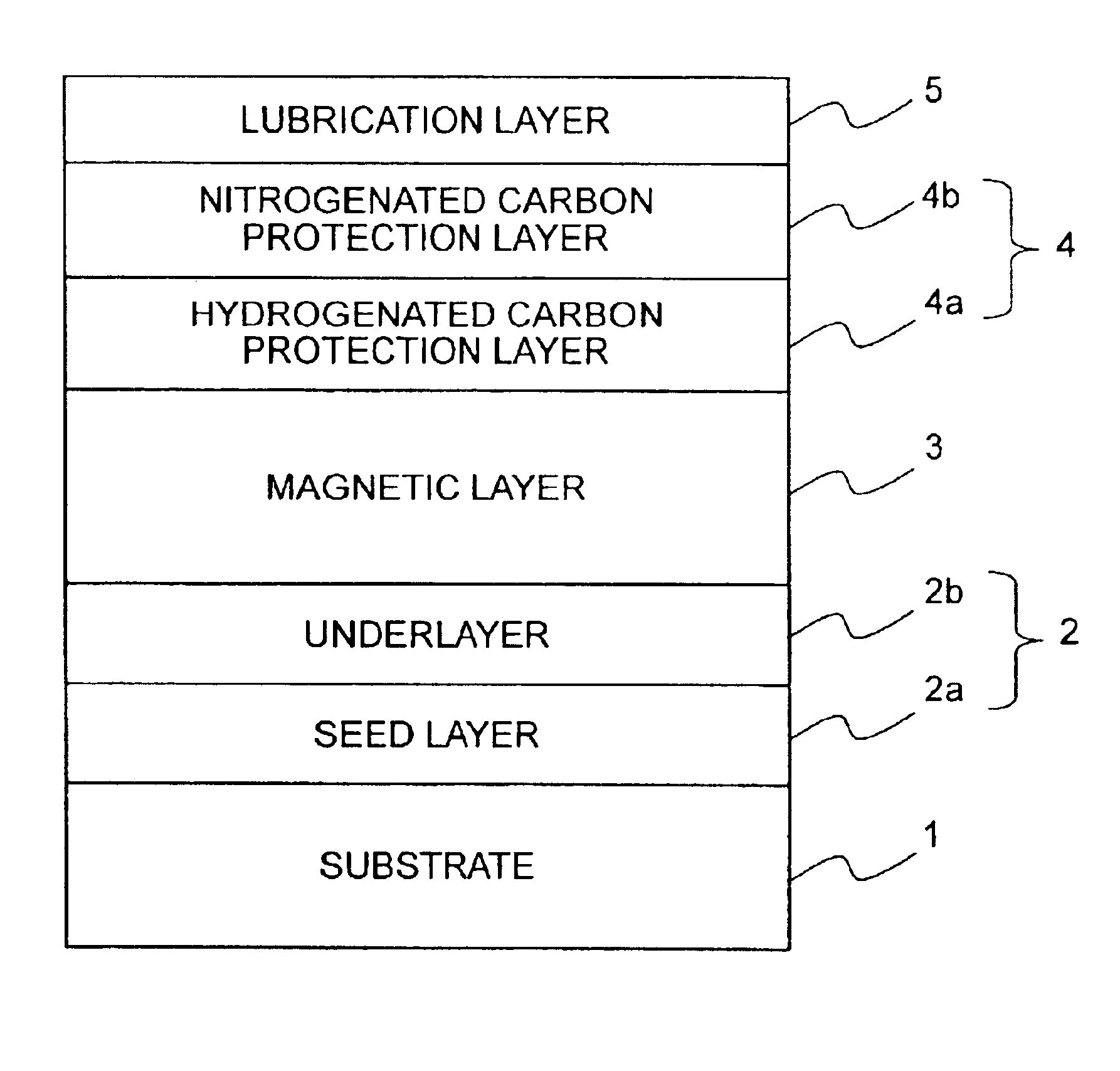
[0098]An aluminosilicate glass was formed into a glass disk blank having a disk-like shape. The glass disk blank was successively subjected to grinding, precision polishing, and precision cleaning. In addition, the glass disk blank was chemically strengthened. As a result, the glass substrate 1 having a flat and clean surface was obtained.

[0099]By the use of an AFM (Atomic Force Microscope), the surface roughness of the glass substrate 1 was precisely measured. In order to obtain the result of measurement with high accuracy, a square area of 5 μm×5 μm was selected as a measured area. Furthermore, each side of the square area was divided into 512 meshes. For each dot, data sampling was carried out.

[0100]As a result, the surface roughness of the glass substrate was 5.04 nm in Rmax, 2.49 nm in Rp, 0.29 nm in Ra, and 0.37 nm in Rq.

[0101]The surface of the glass substrate was measured by a probe-type profilometer (Tencor P2). As a result, the surface profile of the glass substrate was no...

examples 2-5

[0136]In Examples 2-5, magnetic recording media were produced by the use of substrates and a production process similar to those described in conjunction with the magnetic recording medium of Example 1 except the following. Specifically, in Examples 2, 3, 4, and 5, the nitrogenated carbon protection layer 4b was formed by sputtering using a mixed gas containing the Ar gas and the nitrogen gas which had a concentration of 12.5%, 20%, 24%, and 31% so that the content of nitrogen in the nitrogenated carbon protection layer 4b was equal to 5 at %, 7 at %, 8 at %, and 10 at %, respectively. The flow rate of the mixed gas was 40 sccm. The magnetic recording media thus produced were subjected to characteristic evaluation and durability tests similar to those mentioned above. The results are shown in Table 1.

examples 6 and 7

[0137]In Examples 6 and 7, magnetic recording media were produced by the use of substrates and a production process similar to those described in conjunction with the magnetic recording medium of Example 1 except the following. Specifically, in both of Examples 6 and 7, the nitrogenated carbon protection layer 4b was formed by sputtering using a mixed gas containing the Ar gas and the nitrogen gas which had a concentration of 16% so that the content of nitrogen in the nitrogenated carbon protection layer was equal to 6 at %. The flow rate of the mixed gas was 40 sccm. In the magnetic recording medium of Example 6, the nitrogenated carbon protection layer 4b had a thickness of 1 angstrom. In the magnetic recording medium of Example 7, the nitrogenated carbon protection layer 4b had a thickness of 15 angstroms. The magnetic recording media thus produced were subjected to characteristic evaluation and durability tests similar to those mentioned above. The results are shown in Table 1.

[...


PUM

PropertyMeasurementUnit
thicknessaaaaaaaaaa
thicknessaaaaaaaaaa
flying heightaaaaaaaaaa

Abstract

In a magnetic recording medium which comprises a substrate (1), a magnetic layer (3) formed on the substrate, a carbon-based protection layer (4) comprising carbon and formed on the magnetic layer, and a lubrication layer (5) formed on the carbon-based protection layer, the carbon-based protection layer comprises a hydrogenated carbon protection layer (4a) facing the magnetic layer and a nitrogenated carbon protection layer (4b) facing the lubrication layer. The hydrogenated carbon protection layer (4a) comprises carbon and hydrogen. The nitrogenated carbon protection layer (4b) includes no hydrogen but comprises carbon and nitrogen.

Description

BACKGROUND OF THE INVENTION[0001]This invention relates to a magnetic recording medium for recording information and, in particular, to a magnetic disk to be mounted to a HDD (Hard Disk Drive) and the like.[0002]In a conventional magnetic disk drive, use has been made of a CSS (Contact Start and Stop) system. In the CSS system, a magnetic recording head rests on a surface of a magnetic recording medium in contact with its inner-diameter area as a contact sliding zone when the rotation of the magnetic recording medium is stopped. During start-up, the magnetic recording head slides over the contact sliding zone in contact therewith to be slightly lifted up. When the magnetic recording head reaches a read / write zone located outside the contact sliding zone, a read or a write operation is started. In the above-mentioned CSS system, the contact sliding zone is required in addition to the read / write zone.[0003]In the CSS system, the magnetic recording medium is provided with a roughened s...

Claims


Application Information

Patent Timeline
Patent Type & Authority Patents(United States)
IPC IPC(8): G11B5/72
CPCG11B5/72Y10T428/1179Y10T428/265Y10T428/30G11B5/7268G11B5/7266
Inventor MORIKAWA, TAKASHIUMEZAWA, TEIICHIROTOMIYASU, HIROSHIISHIYAMA, MASAFUMI
Owner WD MEDIA SINGAPORE PTE
Why Eureka
Try Eureka