
Magnetic resonance imaging involving movement of patient's couch

a magnetic resonance imaging and patient technology, applied in the direction of measuring using nmr, magnetic variable regulation, instruments, etc., can solve the problems of lack of accuracy, complicated operation, and drawbacks of various types of conventional techniques, so as to speed up imaging, reduce operational work, and increase the accuracy of moving

Inactive Publication Date: 2005-09-20
TOSHIBA MEDICAL SYST CORP
View PDF27 Cites 51 Cited by
  • Summary
  • Abstract
  • Description
  • Claims
  • Application Information

AI Technical Summary

Benefits of technology

[0019]The present invention has been made to overcome the deficiencies of the foregoing imaging techniques. A first object of the present invention is to reduce operational work, speed up imaging, and increasing accuracy in moving a patient's couch when multiple RF coils are used as a reception RF coil so as to perform imaging based on the moving bed technique (method of moving the couch).
[0020]A second object of the present invention is to easily perform the fast imaging with improved temporal resolution, so that MR images of which depiction performance is improved are provided, in cases multiple RF coil are used as a reception RF coil so as to perform imaging based on the moving bed technique.
[0021]Still, a third object of the present invention is to provide fast imaging by moving the couch (tabletop) on which an object is laid, even when only one reception RF coil is used.
[0022]Still further, a fourth object of the present invention is to perform contrast MR angiography at higher speed based on movement of the couch (tabletop) on which an object is laid, thus raising flexibility of the moving bed technique.

Problems solved by technology

However, the above various types of conventional techniques have some drawbacks.
This complicates operations and lacks accuracy, in addition to taking much time.
Further, the current hardware techniques are still lacking when realizing both of the shortened imaging time and the higher temporal resolution.
The foregoing key-hole imaging and other imaging techniques are still short of temporal resolution.
In addition, the foregoing imaging techniques such as the key-hole imaging is simply raising apparent temporal resolution by updating data mapped in part of the k-space, thus lacking a depiction performance of minute structures.
But those techniques are unavailable for imaging that requires the couch to be moved such that different regions are sequentially subject to imaging at a high speed.
However, the moving bed technique involving a single whole-body coil cannot be applied to such fast imaging.
This means that the fast imaging cannot provide its merits satisfactorily.

Method used


Image

  • Magnetic resonance imaging involving movement of patient's couch
  • Magnetic resonance imaging involving movement of patient's couch
  • Magnetic resonance imaging involving movement of patient's couch

Examples


first embodiment

[0056]Referring to FIGS. 3 and 4, a magnetic resonance imaging (MRI) system of a first embodiment will now be described.

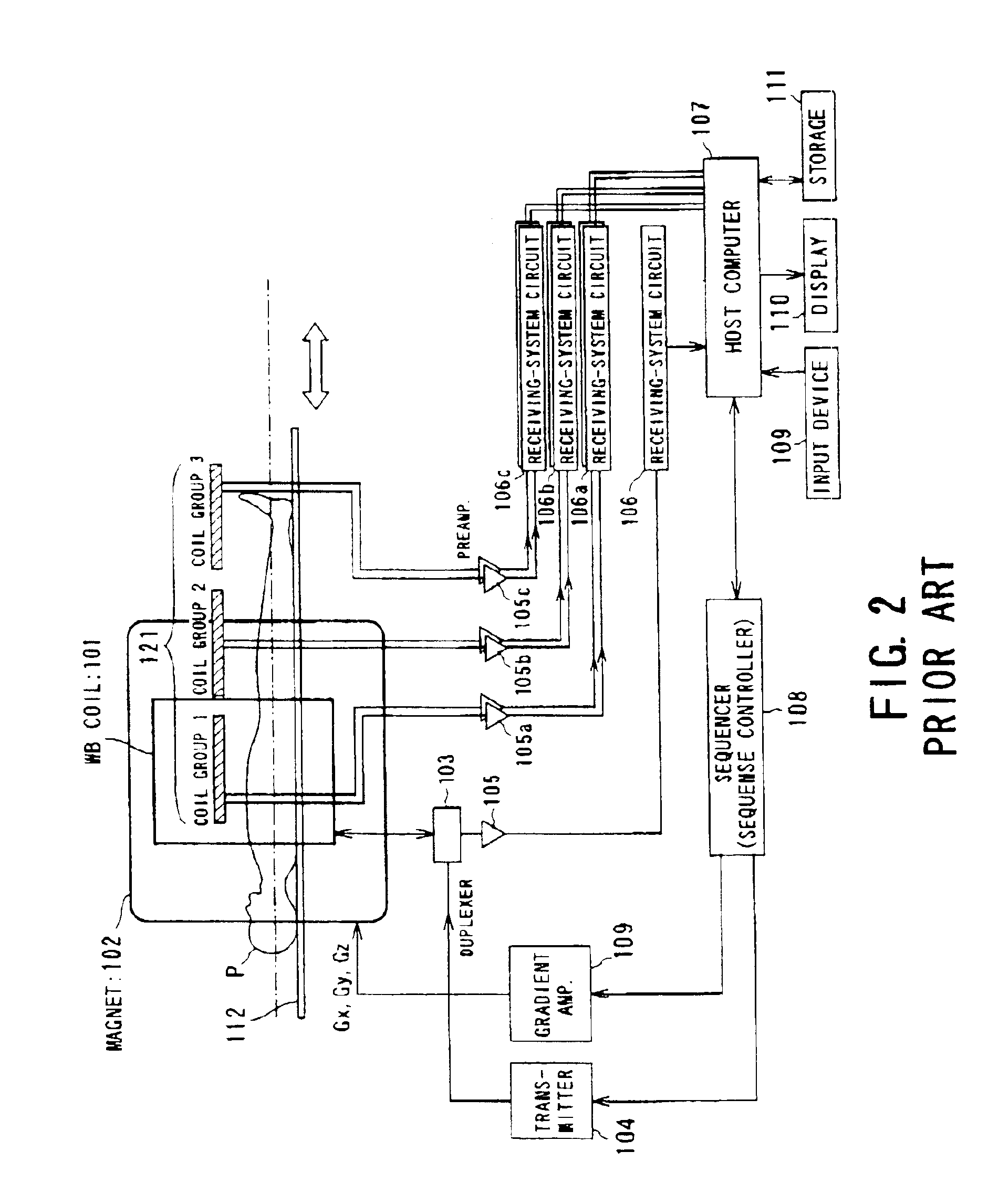
[0057]The magnetic resonance imaging system performs imaging using multiple RF coils with a moving couch (that is, a moving bed technique).

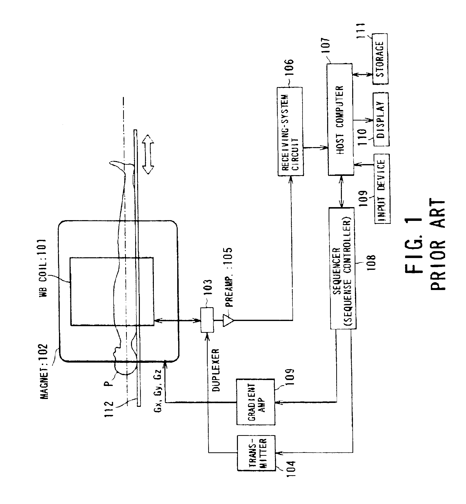
[0058]The configuration of this magnetic resonance imaging system is outlined in FIG. 3. This system has a couch unit on which a patient P as an object to be imaged, a static magnetic field generating unit for generating a static magnetic field, and a gradient generating unit for adding position information to the static magnetic field. The system also has a transmission / reception unit for transmitting and reception RF signals and a control / calculation unit in charge of control of the entire system and image reconstruction.

[0059]The static magnetic generation unit is proved with a magnet 1 constructed by employing for example a superconducting magnet and a static power supply 2 supplying current to the magnet 1. By these devices...

seventh embodiment

[0130]Referring to FIGS. 15 to 18, another embodiment of the present invention will now be described. Like the seventh embodiment, this embodiment is characterized by fast imaging based on changes in sensitivity distributions of one or more reception coils when a couch is moved.

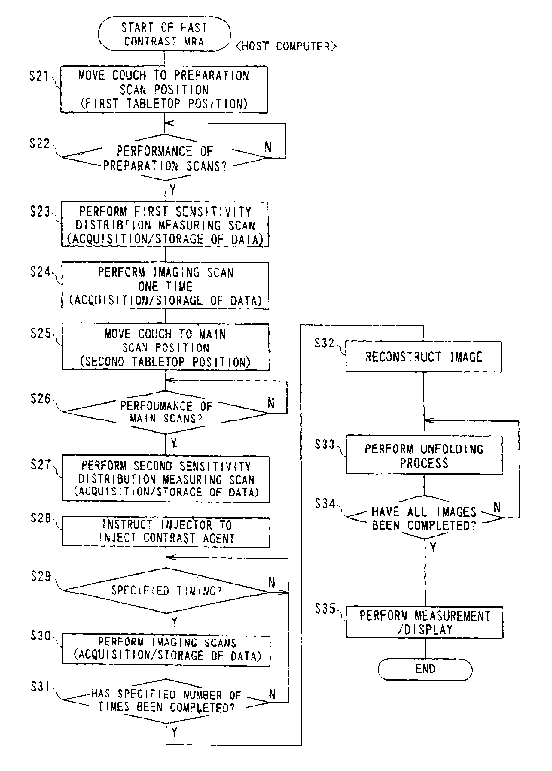
[0131]Particularly one preferred embodiment of the fast imaging is fast contrast MR angiography (MRA) carried out under injection of an MR contrast agent in order to obtain images and / or measurement information in which its contrast effect is reflected.

[0132]The present embodiment will be described about a configuration in which the foregoing fast imaging is performed as the fast contrast MR angiography, but the configuration is not limited to such fast contrast MRA.

[0133]FIG. 15 shows a schematic form of a magnetic resonance imaging system capable of performing the fast contrast MRA. This system includes, as shown in FIG. 15, a whole-body (WB) coil 7T serving as a transmission coil and a single reception coi...

eighth embodiment

[0153]The imaging has been described with respect to an MRA in the above embodiment, but the imaging using a single reception coil can be carried out with no injection of a contrast agent. In such a case, the fast imaging may be performed on the sub-encoding method, although the reception coil is one in number. In other words, like the above eighth embodiment, a region to be imaged may be moved relatively to the one reception coil, so that a plurality of sets of echo data whose sensitivity to the reception RF coil is changed set by set are obtained. This is virtually equivalent to a configuration in which two reception coils are used.

[0154]Although the eighth embodiment has used one reception coil, this embodiment is able to adopt two or more reception coils. In cases the number of reception coils is increased, the speed of imaging can be doubled under a limitation that the same region can be imaged.

[0155]Further, a whole-body coil for transmission / reception can be used.

[0156]In the...


PUM


Abstract

A magnetic resonance imaging system performing various types of imaging that involves movement of a patient's couch. The system has a patient's couch having a tabletop movable in a predetermined direction passing through a static magnetic field as well as reception multiple RF coils consisting of for example a plurality of coil groups. The tabletop is automatically moved in its longitudinal direction in accordance with a length of each coil group in the predetermined direction. At each moved position, scanning is performed on a given pulse sequence. An echo signal is received through the multiple RF coils, then switched over by an input switchover unit to be sent to a receiving-system circuit. The echo signal is subjected to given processing in this circuit so that it is converted to echo data. The echo data are produced into an MR image by a host computer.

Description

BACKGROUND OF THE INVENTION[0001]1. (Field of the Invention)[0002]The present invention relates to a magnetic resonance imaging (MRI) system and a magnetic resonance imaging method, which are used for medical purposes, and in particular, to a system and method enabling fast and / or wide-range imaging with a couch (tabletop) on which a patient (object to be imaged) is laid.[0003]2. (Description of Related Art)[0004]Magnetic resonance imaging is a technique for magnetically exciting nuclear spins in an object located in a static magnetic field by applying a radio-frequency (RF) signal with the Larmor frequency, and reconstructing an image of the object using an FID (free induction decay) signal or echo signal induced by the excitation. In the field of magnetic resonance imaging, like imaging using other modalities, a wide variety of imaging techniques have been developed thanks to recent advancements in hardware.[0005]For example, for imaging blood vessels in the inferior limb, various...

Claims


Application Information

Patent Timeline
Patent Type & Authority Patents(United States)
IPC IPC(8): G01R33/563G01R33/54G01R33/28
CPCG01R33/5611G01R33/56383G01R33/56375G01R33/5635G01R33/543
Inventor KUHARA, SHIGEHIDE
Owner TOSHIBA MEDICAL SYST CORP
Learn More