Magnetic resonance imaging method and apparatus with spatial coding using readout segmentation

Inactive Publication Date: 2005-09-20
SIEMENS HEALTHCARE GMBH
View PDF5 Cites 20 Cited by
  • Summary
  • Abstract
  • Description
  • Claims
  • Application Information

AI Technical Summary

Benefits of technology

[0015]An object of the present invention is to provide an imaging procedure for magnetic resonance tomography that has improvements over the imaging procedures described above. The improvements include, among other things, a decrease in the susceptibility artifacts and a lower sensitivity with respect to dynamic field changes compared to EPI as well as a less complex signal modulation in k-space compared to GRASE, which then leads to fewer ring and ghost artifacts. Furthermore, a lower specific absorption rate (SAR) is described as well as fewer artifacts with respect to movement-induced phase shifts with diffusion-weighted imaging.

Problems solved by technology

The scanning of the k matrix (or k matrices in the case of data acquisition from several layers) for spin echo sequences with diagnostically usable image quality normally requires several minutes of measurement time, was can be a problem for many clinical application.
For examinations of the thorax or in the pelvic region movement of the anatomy is generally unavoidable (cardiac and respiratory movements, peristalsis).

Method used


Image

  • Magnetic resonance imaging method and apparatus with spatial coding using readout segmentation
  • Magnetic resonance imaging method and apparatus with spatial coding using readout segmentation
  • Magnetic resonance imaging method and apparatus with spatial coding using readout segmentation

Examples


Embodiment Construction

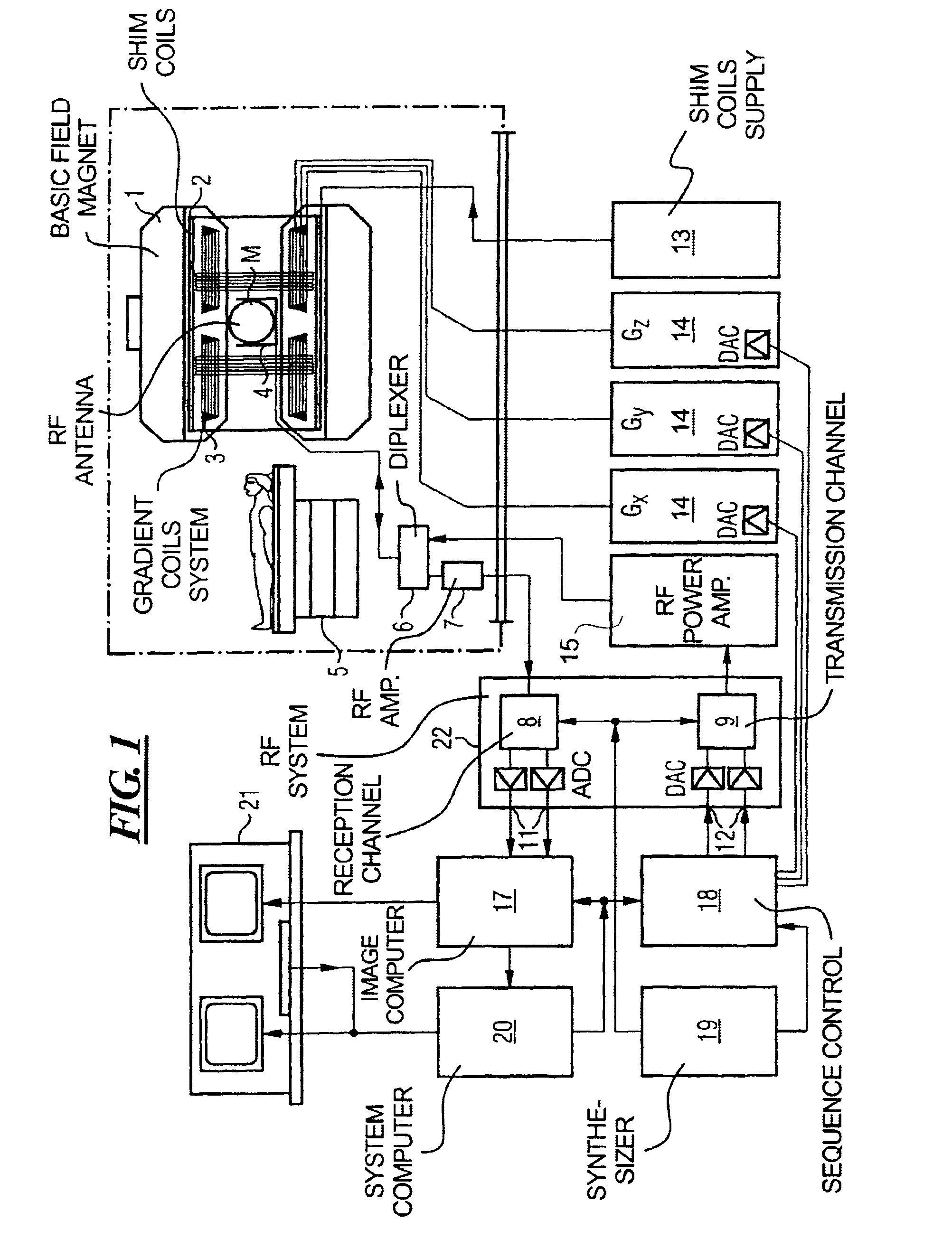
[0034]FIG. 1 schematically illustrates an MRT apparatus for the implantation of the present invention. The basic components of the MRT apparatus correspond to the known arrangement for MRT systems, with the differences discussed in detail below. A basic field magnet 1 generates a chronologically constant strong magnetic field for the polarization or alignment of the nuclear spin in the area under examination of an object, e.g. a part of a human body to be examined. The high degree of homogeneity of the basic magnetic field required for the magnetic resonance data acquisition is defined in a spherical measurement volume M, into which the part of the human body to be examined is inserted. For the support of the homogeneity requirements and in particular for the elimination of chronologically invariable influences, shim plates made of ferromagnetic material are attached at suitable locations. Chronologically variable factors are eliminated by shim coils 2, which are controlled by a shi...


PUM


Abstract

In a method and apparatus for magnet resonance imaging, and RF excitation pulse is emitted for the excitation of spins in an object to be examined and simultaneously a slice-selection gradient is activated during the RF excitation pulse, a pulse series of refocusing pulses is emitted, a slice-selection gradient pulse is activated during each refocusing pulse, and alternating readout gradient pulse series are activated, each series being in the pulse between two refocusing pulses, with a de-phasing pulse being activated immediately before each readout gradient pulse series and a re-phasing pulse being activated immediately after the each readout gradient pulse series such that a corresponding offset is produced in the readout direction so that each readout gradient pulse series scans a part of the k-matrix in the kx direction in a serpentine-like manner, with the serpentine-like scanning of each partial section being implemented by activating short phase-coding gradient pulses during each zero point of the corresponding readout-gradient pulse series.

Description

BACKGROUND OF THE INVENTION[0001]1. Field of the Invention[0002]The present invention concerns, in general, the magnetic resonance tomography (MRT) as used in medicine to examine patients. The present invention concerns, in particular, an MRT imaging procedure for the acquisition of high-resolution single-shot images in a short scanning period.[0003]2. Description of the Prior Art[0004]MRT is based on the physical phenomenon of nuclear spin resonance and has been successfully employed in medicine and biophysics as an imaging procedure for more than 15 years. In this modality, the object is exposed to a strong, constant magnetic field. The nuclear spins of the atoms, which were previously randomly oriented, thereby are aligned in the object. Radio-frequency energy can then excite these “ordered” nuclear spins to a specific oscillation. This oscillation creates the actual measurement signal in MRT, which is recorded using suitable receiving coils. By the use of inhomogeneous magnetic ...

Claims


Application Information

Patent Timeline
IPC IPC(8): G01R33/561G01R33/54
CPCG01R33/5615
Inventor PORTER, DAVID ANDREW
Owner SIEMENS HEALTHCARE GMBH
Why Eureka
Try Eureka