Video scope utilized in electronic endoscope system

a video scope and endoscope technology, applied in the field of video scope utilized in electronic endoscope systems, can solve the problems of unused wiring patterns, noise radiation, and the inability of first and second types of video signals to be directly fed to the video signal processing unit, and achieve the effect of reducing the radiation of noise from unused wiring patterns

Inactive Publication Date: 2005-09-20
ASAHI KOGAKU KOGYO KK
View PDF5 Cites 54 Cited by
  • Summary
  • Abstract
  • Description
  • Claims
  • Application Information

AI Technical Summary

Benefits of technology

[0017]Therefore, an object of the present invention is to provide a video scope utilized in an electronic endoscope system and containing a circuit board, in which an unused-wiring pattern, remaining on the circuit board, is treated such that radiation of noise from the unused wiring-pattern is reduced as much as possible.

Problems solved by technology

Nevertheless, in reality, the first and second types of video signals cannot be directly fed to the video-signal processing unit, because each of the wiring-patterns is cut off at a suitable location.
In this case, the unused wiring-patterns are partially supplied with either the first type of video signals or the second type of video signals, and thus may radiate noise because the video signals are similar to high frequency signals.
When the unused wiring-pattern is supplied with the basic clock pulse, i.e. high frequent pulses, the unused wiring-pattern may form a noise-radiation source.

Method used


Image

  • Video scope utilized in electronic endoscope system
  • Video scope utilized in electronic endoscope system
  • Video scope utilized in electronic endoscope system

Examples


first embodiment

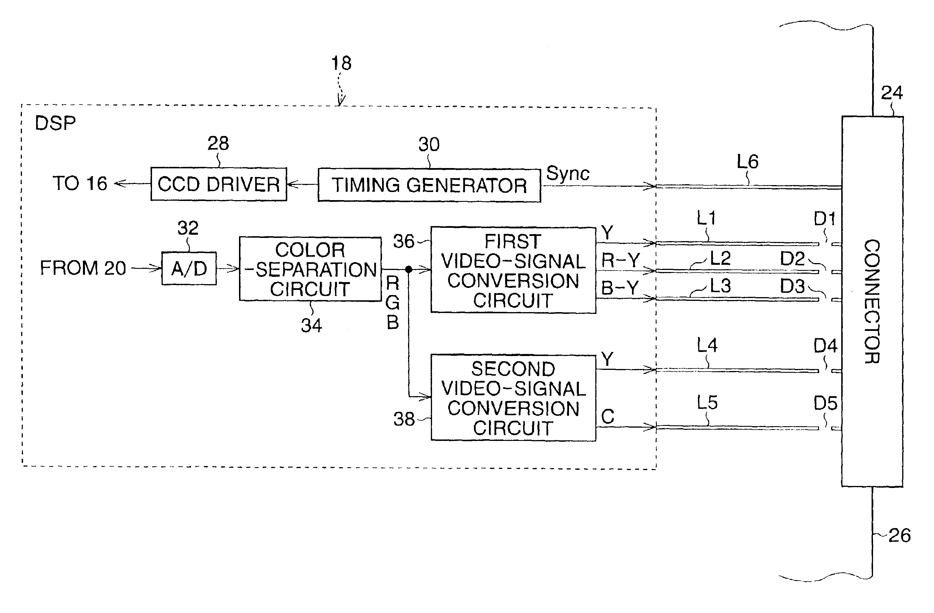
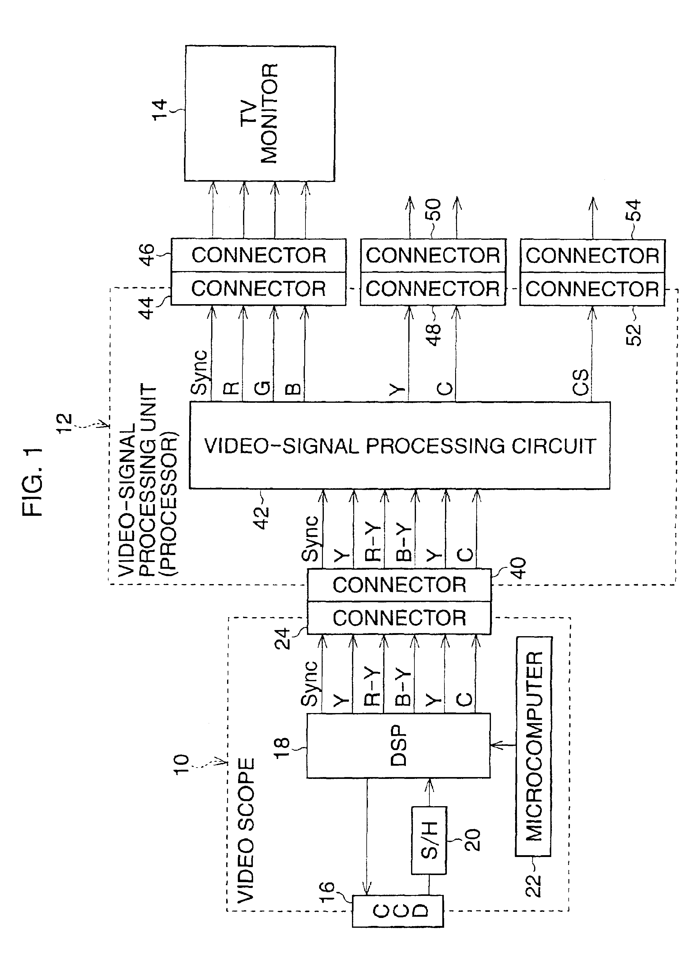
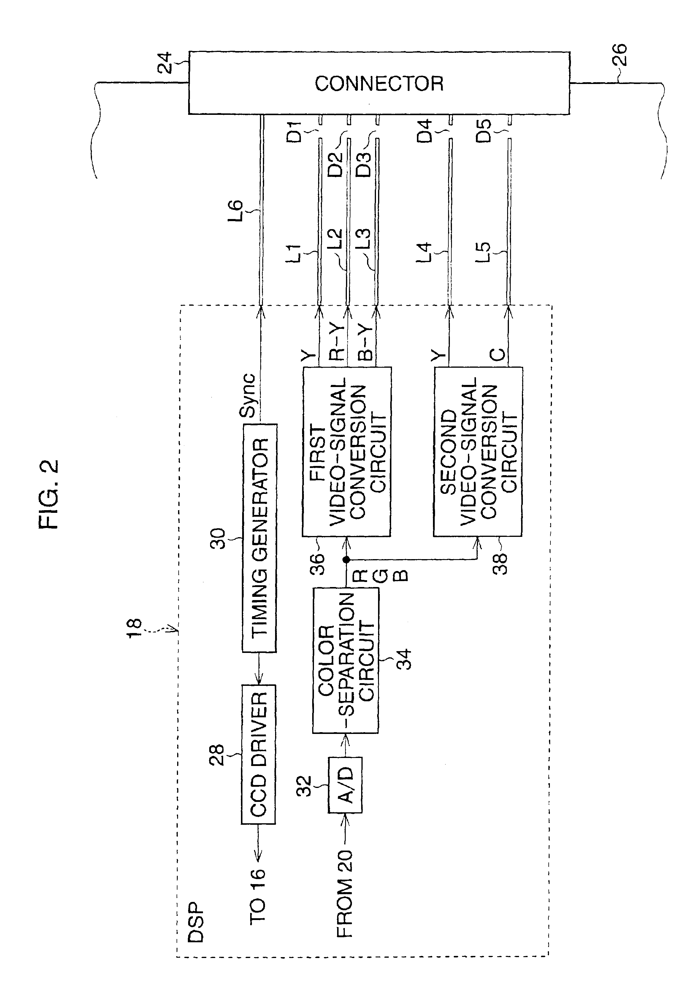
[0039]With reference to FIG. 1, an electronic endoscope system is schematically shown as a block diagram, in which a video scope according to the present invention, generally indicated by reference 10, is incorporated. Namely, the video scope 10 forms a part of the electronic endoscope system, and the electronic endoscope system further comprises a video-signal processing unit or processor 12 to which the video scope is detachably coupled, and a TV monitor 14 connected to the video-signal processing unit 12.

[0040]The video scope 10 has a rigid manipulating-section, and a flexible conduit section extending from the rigid manipulating-section. The flexible conduit section of the video scope 10 has a solid-state image sensor 16, such as a CCD (charge-coupled device) image sensor, provided at a distal end thereof, and is inserted in an organ of a human body for medical examination. Although not illustrated, the video scope 10 includes a flexible optical light guide extending therethroug...

second embodiment

[0070]With reference to FIG. 5, an electronic endoscope system is schematically shown as a block diagram, in which a video scope according to the present invention, generally indicated by reference 110, is incorporated. Namely, the video scope 110 forms a part of the electronic endoscope system, and the electronic endoscope system further comprises a video-signal processing unit or processor 112 to which the video scope is detachably coupled, and a TV monitor 114 connected to the video-signal processing unit 112.

[0071]Similar to the first embodiment, the video scope 110 has a rigid manipulating-section, and a flexible conduit section extending from the rigid manipulating-section. The flexible conduit section of the video scope 110 has a solid-state image sensor 116, such as a CCD (charge-coupled device) image sensor, provided at a distal end thereof, and is inserted in an organ of a human body for medical examination. Although not illustrated, the video scope 110 includes a flexible...


PUM


Abstract

A video scope has an image sensor, a circuit board, and a digital signal processor mounted on the circuit board. The digital signal processor reads image signals from the image sensor, and processes the read image signals to thereby produce at least two types of video signal. A wiring-pattern is formed on the circuit board to feed a video signal component, included in one of the two types of video signals, from the digital signal processor. The wiring-pattern is cut off at a suitable location. When the wiring-pattern remains as an unused wiring-pattern on the circuit board, the wiring-pattern is treated such that radiation of noise is prevented from going through the unused wiring-pattern.

Description

BACKGROUND OF THE INVENTION[0001]1. Field of the Invention[0002]The present invention relates to a video scope utilized in an electronic endoscope system, and, in particular, is directed to treatment for unused circuit patterns on an electronic circuit board incorporated in such a video scope.[0003]2. Description of the Related Art[0004]As is well known, an electronic endoscope system includes a video scope or so-called electronic scope, and a video-signal processing unit or so-called processor, to which the video scope is detachably coupled. The video scope has a rigid manipulating-section, and a flexible conduit section extending from the rigid manipulating-section.[0005]The flexible conduit section of the video scope has a solid-state image sensor, such as a CCD (charge-coupled device) image sensor, provided at a distal end thereof, and is inserted in an organ of a human body for medical examination. To illuminate an object to be sensed by the CCD image sensor, the video scope in...

Claims


Application Information

Patent Timeline
Patent Type & Authority Patents(United States)
IPC IPC(8): H04N5/335H04N5/217H04N5/225H05K1/02
CPCH04N5/217H04N5/335H04N2005/2255H05K1/0216H04N23/81H04N23/555H04N25/00
Inventor TAKAMI, SATOSHIISHIZUKA, YUKIHIRO
Owner ASAHI KOGAKU KOGYO KK
Why Eureka
Try Eureka