Fabry-perot etalon with independently selectable resonance frequency and free spectral range

a technology of etalon and resonance frequency, applied in the field of optical interference filters, can solve the problems of imposing substantial physical limitations on the speed of information transmission and utilization, and affecting the overall efficiency and accuracy of the telecommunication network. achieve the effect of high and low refractive index, desirable discriminator slope, and high and low finess

Inactive Publication Date: 2005-09-20
EXCELITAS TECH
View PDF32 Cites 22 Cited by
  • Summary
  • Abstract
  • Description
  • Claims
  • Application Information

AI Technical Summary

Benefits of technology

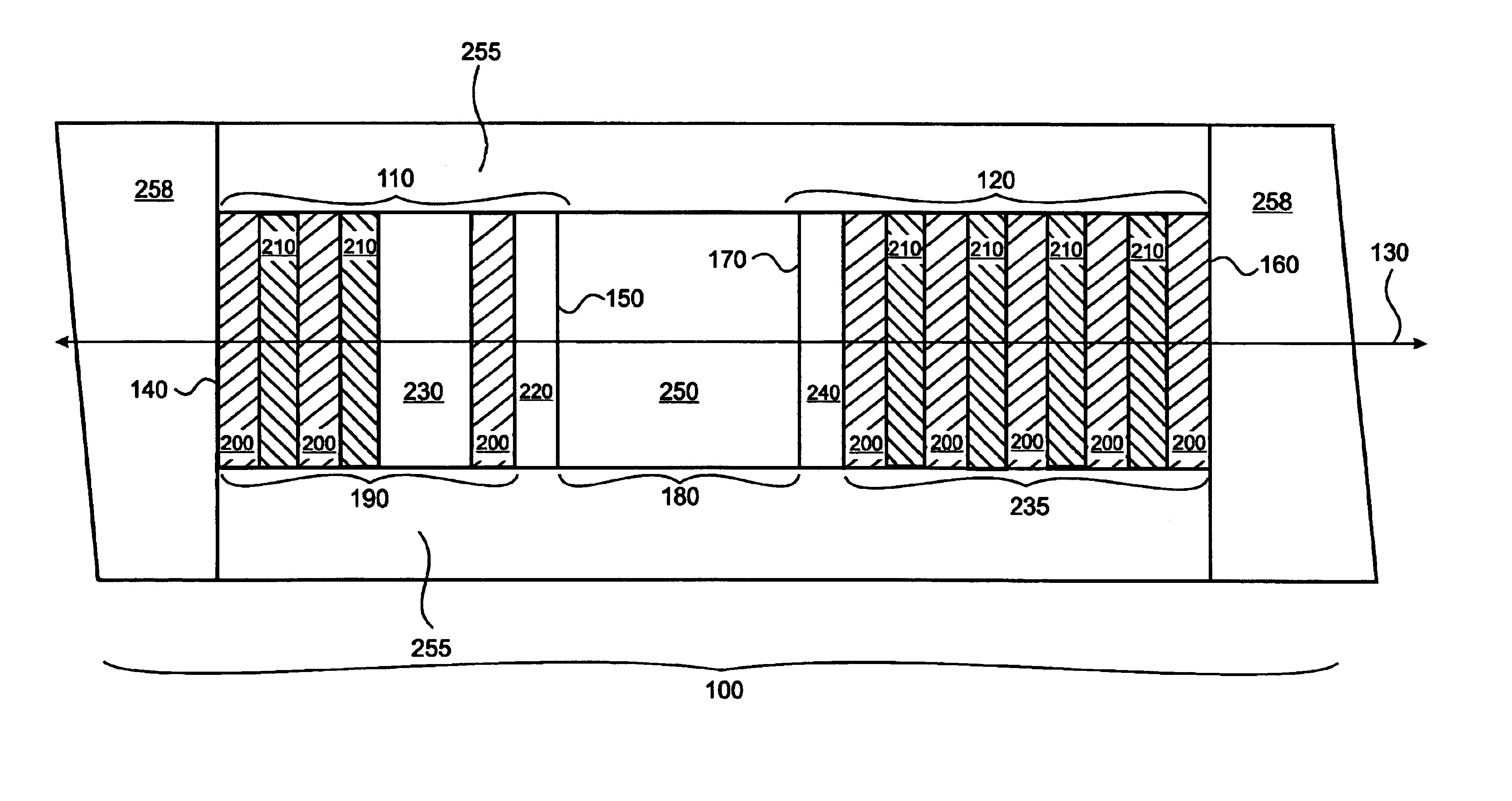
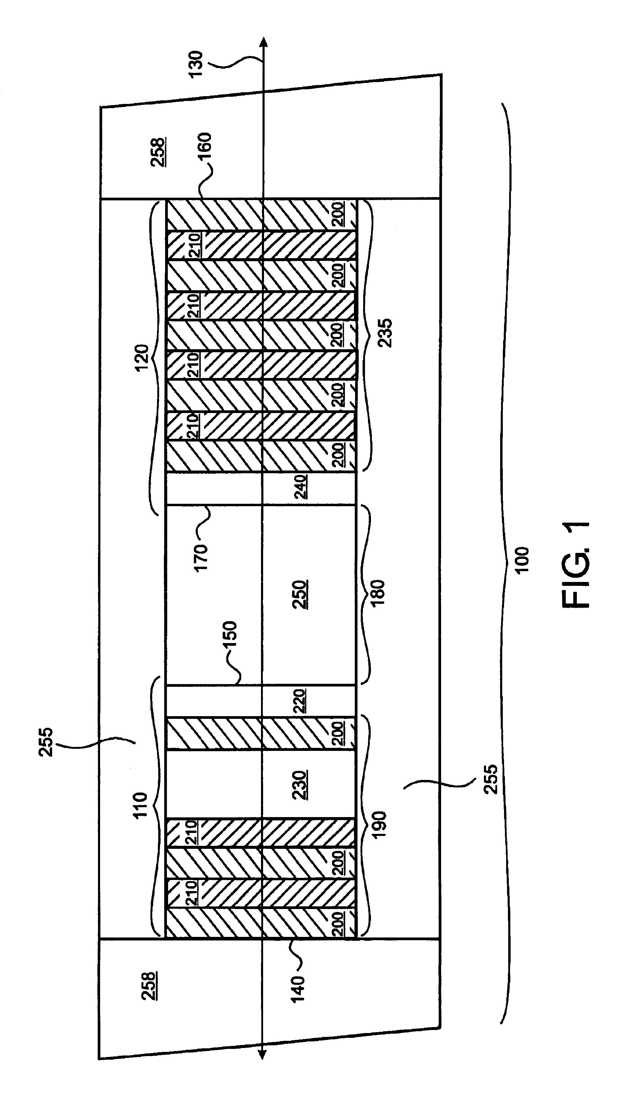
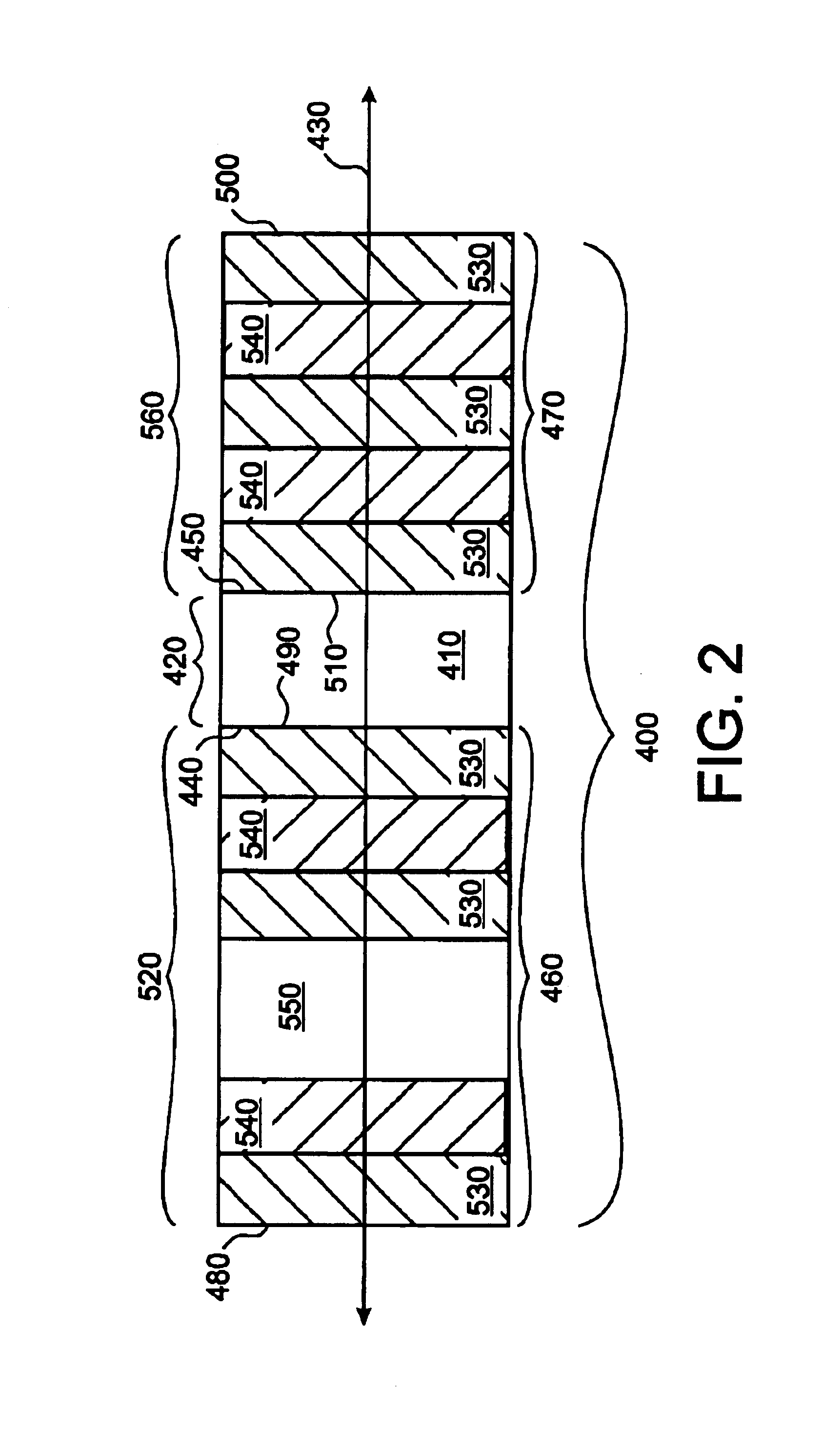
[0019]An optical interference filter of the present invention comprises a FP etalon filter with substantially independent, selectable control of the resonance frequency and free spectral range. In this embodiment, the FP etalon filter has a selected cumulative reflectance phase dispersion, which provides the desired transmission characteristics. Specifically, selection of the cumulative reflectance phase dispersion provides accurate control of the resonance frequency and the free spectral range of the FP etalon filter. As result of this functionally, an FP etalon filter of the present invention is capable of providing a multi-peaked transmission spectrum wherein the frequencies of transmission bands and the relative spacing between transmission bands are substantially independently selectable. In a preferred embodiment, the FP etalon filters of the present invention are capable of providing substantially periodic transmission bands. Specifically, this embodiment provides a reflection phase shift at each reflector that is substantially linear with respect to the frequency of incident radiation. Substantial linearity of the reflection phase shift with respect to frequency is achieved by providing reflectors that exhibit substantially constant reflectance as a function of frequency. Optical filters having periodically spaced transmission bands are beneficial because they may be frequency matched with the evenly spaced channels of a frequency standard or evenly spaced emission lines of a given optical source.
[0037]The GT etalon filter of the present invention operates by multiple-beam interference of light reflected and transmitted by first partial reflective reflector and second highly reflective reflector. Specifically, an incident light beam directed on to the GT etalon filter undergoes partial reflection and partial transmission upon interaction the first reflector. The transmitted portion propagates through the resonance cavity and substantially all the light is reflected by the second reflector. The plurality of beams formed undergoes constructive or destructive interference as they propagate in GT etalon. Importantly, the beams also interact with one or more absentee layers, which increase the cumulative reflectance phase dispersion experienced. Preferred increases in cumulative reflectance phase dispersion in the GT etalon filter of the present invention range from about 1.0×10⁻⁶ rad / GHz to about 1.0×10⁻³ rad / GHz. More preferred increases in cumulative reflectance phase dispersion range from about 1.0×10⁻⁶ rad / GHz to about 5.0×10⁻⁵ rad / GHz. In a preferred embodiment, the cumulative reflectance phase dispersion is selected to provide a selected phase dispersion, which establishes the transmission properties of the etalon filter.

Problems solved by technology

The parallel optical configuration of the FP etalon provides for multiple reflections, which results in constructive and / or destructive interference depending on the wavelength of light propagating through the cavity.
While such telecommunication systems exploit the substantial efficiency gains of using optical methods for signal transmission, signal processing via standard electronic techniques remains a barrier to achieving the highest overall efficiency and accuracy of the telecommunication network.
Specifically, the use of electronic components for signal processing often imposes substantial physical limitations on the speed that information can be transmitted and utilized.
While the periodic nature of the transmission spectra of FP etalon filters makes them ideally suited for wavelength discrimination in multiplex applications employing equally spaced transmission channels, their use is currently hampered by fundamental spectral limitations impeding accurate frequency matching of the transmission bands of a standard FP etalon filter with the transmission channels defined by the ITU frequency standard.
These spectral limitations include the inability of FP etalon filters of the prior art to have the appropriate free spectral range and resonance frequency to overlap the transmission channels of the ITU frequency standard.
As a result, most FP etalon designs currently available do not provide independent and selectable control of free spectral range and resonance frequency.
Unfortunately, these designs do not provide FP etalon filters with transmission spectra that match the channel spacing and position of the universally adopted ITU frequency standard.
While the resonance frequency is reported to vary systematically with angle of incidence and cavity temperature, the etalon described in U.S. Pat. No. 5,212,584 does not provide substantially independent selectable resonance frequency and free spectral range.
Accordingly, U.S. Pat. No. 5,212, 584 does not disclose methods of frequency matching the transmission bands of an etalon optical filter with the plurality of transmission channels or emission lines of a given frequency standard, such as the ITU frequency grid.
While U.S. Pat. No. 5,291,332 reports successful frequency matching of the etalon transmission spectra and aperiodic atmospheric spectral lines, the reference does not disclose methods of frequency matching periodic spectral lines.
Particularly, the reference does not disclose or suggest devices or methods capable of independently adjusting etalon resonance frequency and free spectral range while preserving a substantially periodic transmission spectrum.
Further, the reference does not disclose techniques for frequency matching etalon transmission spectra and the evenly spaced transmission lines of given frequency standard or the evenly spaced lines of an optical source.
Finally, the etalon design described in U.S. Pat. No. 5,291,332 employs costly rugate reflectors that are difficult to manufacture.
Although the mirror structures disclosed are reported to provide reflection at selected frequencies, U.S. Pat. No. 6,154,318 does not disclose optical methods for frequency filtering employing Fabry-Perot interferometry.
Further, the methods disclosed are limited to the use of multilayer mirror structures for pulsed optical source applications.
Finally, the methods and devices disclosed by the authors to achieve the desired resonance trapping properties are limited to “resonant substructures arranged around layers less than one quarter-wavelength optical thickness.”

Method used


Image

  • Fabry-perot etalon with independently selectable resonance frequency and free spectral range
  • Fabry-perot etalon with independently selectable resonance frequency and free spectral range
  • Fabry-perot etalon with independently selectable resonance frequency and free spectral range

Examples


example 1

FP Etalon Filter Frequency Matched to the Transmission Channels of the ITU Frequency Standard

[0087]The ability of the optical interference filter of the present invention to be frequency matched to the transmission channels of the ITU transmission grid was evaluated and compared to etalon designs in the prior art. The standard channel definition of the ITU frequency standard provides for a 45 channel system over a wavelength range of 1533 nm to 1565 nm with a uniform channel spacing of 100 GHz (approximately 0.8 nm). Therefore, it is a goal of the present invention to design an optical interference filter with a 100 GHz free spectral range and with resonance frequency positions matched to the ITU frequency standard. Further, the spacing of resonance peaks must be matched to the desired reference spacing to a very high degree of accuracy, commonly 1-5 ppm, to ensure efficient and accurate signaling. Accordingly, an optimal etalon must have a free spectral Range of 100 GHz, correspond...

example 2

GT Etalon Filter Frequency Matched to the Transmission Channels of the ITU Frequency Standard

[0094]A GT etalon of the present invention capable of frequency matching to the transmission channels of the ITU frequency grid was evaluated and compared to GT etalon designs in the prior art. Specifically, a GT etalon was designed to have a free spectral range a close as possible to 50 GHz and a resonance frequency as close as possible to a frequency of 194000 GHz. Further, the GT etalon was designed to comprise a partial reflector with a reflectance of approximately 48% at one mirror and a high reflector with a reflectance of 99.95%.

[0095]Prior art GT etalon designs with a free spectral as close as possible to 50 GHz and a resonance frequency as close as possible to a frequency of 194000 GHz comprises a partially reflective reflector and highly reflective reflector separated by a resonance cavity with an optical path length of approximately 3.0 mm. Specifically, the partially reflective r...


PUM


Abstract

The invention relates generally to optical interference filters and interferometers. Methods, devices and device components for optical signal generation and processing using optical interference filters and interferometers are presented. The invention provides optical interference filters and interferometers having a selected cumulative reflectance phase dispersion capable of providing substantially independent selectable resonance frequency and free spectral range. An exemplary interference filter of the present invention provides a multi-peak transmission spectrum with substantially independent, selectable control over absolute transmission band frequencies and relative transmission band spacing. The methods and devices provided herein are particularly well suited for frequency matching optical signals to a selected frequency standard, such as the International Telecommunication Union frequency standard.

Description

FIELD OF INVENTION[0001]This invention relates generally to optical interference filters and devices and device components employing optical interference filters. In particular, the invention relates to Fabry-Perot optical interference filters with a selected cumulative reflectance phase dispersion capable of providing substantially independent, selectable resonance frequency and free spectral range, which are useful for frequency matching optical signals to a particular frequency standard.BACKGROUND OF INVENTION[0002]The Fabry-Perot (FP) interferometer has played a seminal role in the development of a number of scientific fields including atomic and molecular spectroscopy, material science, astronomy, lasers and optical communications. Fabry-Perot etalons are optical filters based on the FP interferometer. These filter are capable of providing extremely high resolution approaching tens of megaHertz at optical frequencies, very high light throughput and can comprise active optical c...

Claims


Application Information

Patent Timeline
Patent Type & Authority Patents(United States)
IPC IPC(8): G02B5/28
CPCG02B5/284
Inventor TURNER, III, NELSON C.
Owner EXCELITAS TECH
Why Eureka
Try Eureka