
Providing a temperature dependent bias for a device

a technology of temperature dependent bias and bias, which is applied in the direction of push-pull amplifiers, phase splitters, transmission, etc., can solve the problems of large gain variations of certain pas at different temperatures, negatively affecting the linearity characteristics of pa, etc., and achieves substantial linearity and reduces the variation of a gain characteristic curve

Inactive Publication Date: 2013-04-30
AVAGO TECH INT SALES PTE LTD
View PDF12 Cites 5 Cited by
  • Summary
  • Abstract
  • Description
  • Claims
  • Application Information

AI Technical Summary

Benefits of technology

The patent describes a system that can create a radio signal from a baseband processor with minimal changes in signal strength caused by changes in temperature. This is achieved by generating a bias current for the amplifier that can have multiple profiles at different temperatures. As a result, the system can maintain linearity and minimize signal loss even when temperatures change.

Problems solved by technology

However, certain PAs can suffer from large gain variations at different temperatures, if not supplied with a temperature dependent bias.
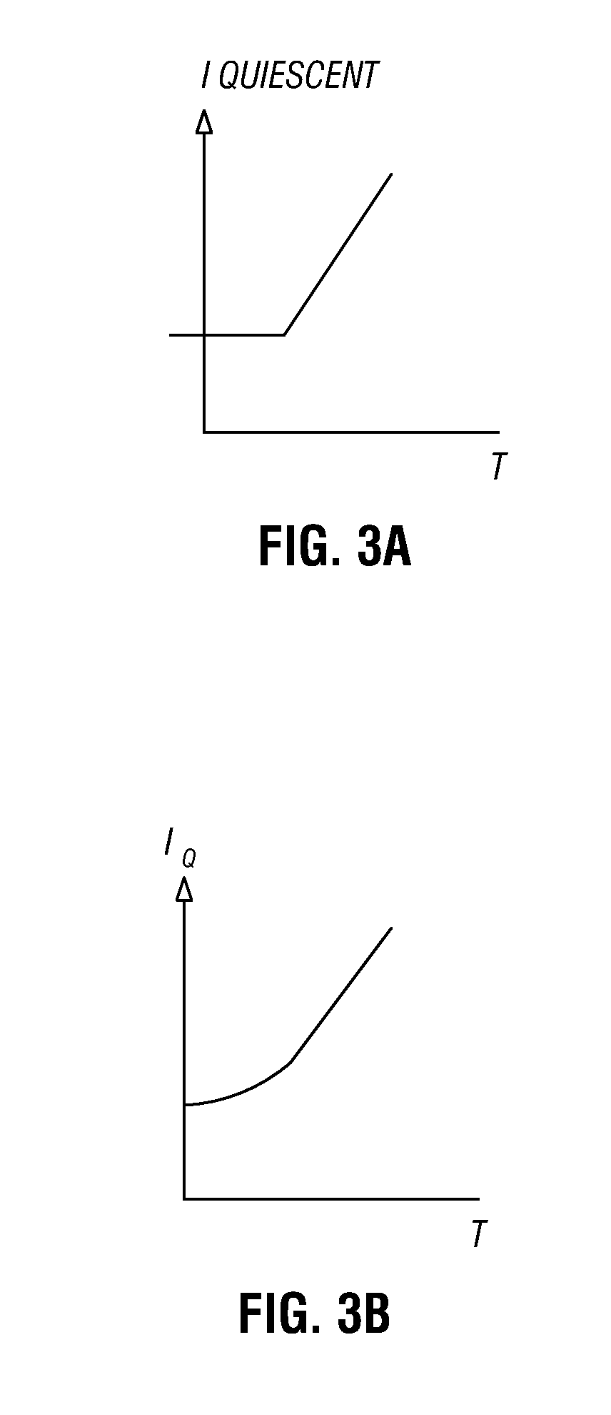
However, this temperature dependent current can negatively impact linearity characteristics of the PA.

Method used


Image

  • Providing a temperature dependent bias for a device
  • Providing a temperature dependent bias for a device
  • Providing a temperature dependent bias for a device

Examples


Embodiment Construction

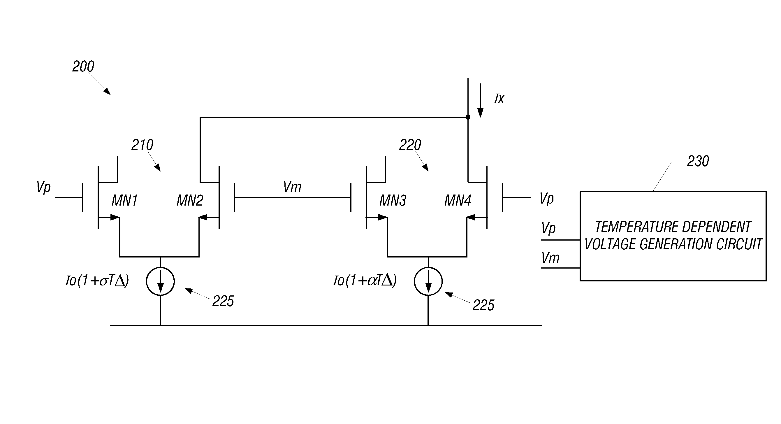
[0014]In various embodiments, a technique may provide a temperature dependent bias for an amplifier, e.g., a gain stage of a PA. By providing a temperature dependent bias, the output of the gain stage may have reduced gain variation across a temperature profile at which the device may operate, while maintaining desired gain characteristic curves which are related to linearity. Specific circuits for providing this temperature dependent bias will be discussed further below.

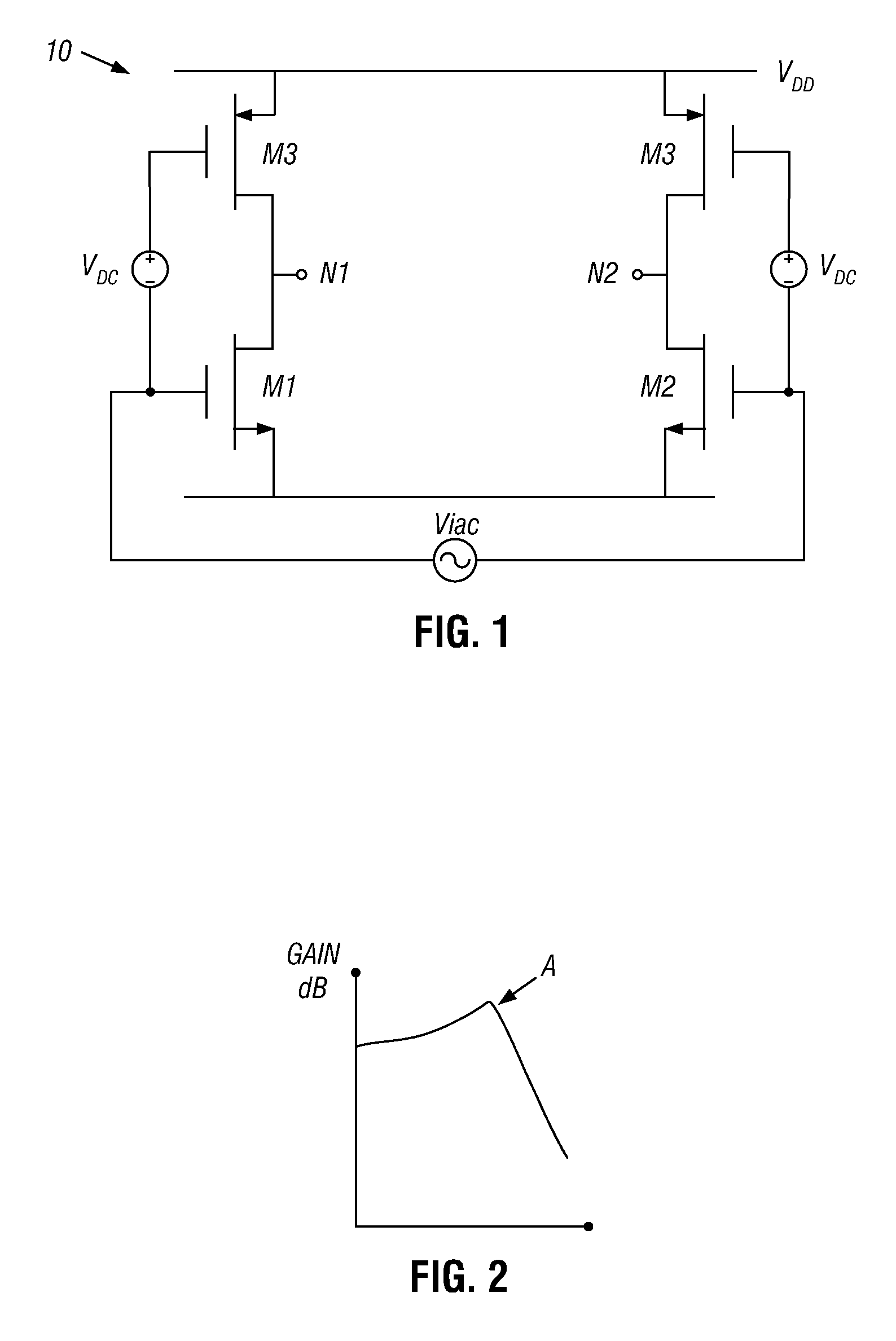
[0015]However, a discussion of an example amplifier and the gain variation that is possible over a temperature profile first discussed. Referring now to FIG. 1, shown is a schematic diagram of an example gain stage. In the embodiment of FIG. 1, gain stage 10, which may be one of multiple gain stages of a PA such as a complementary metal-oxide-semiconductor (CMOS) PA, may be formed of complementary pairs of metal-oxide-semiconductor field effect transistors (MOSFETs) M1-M4 configured as a differential H-bridge. As se...


PUM


Abstract

In one embodiment, a method includes generating a first current in a bias current circuit and biasing an amplifier with the first current when the amplifier is operating in a first temperature range, and generating a second current in the bias current circuit and biasing the amplifier with the second current when the amplifier is operating in a second temperature range. These two currents may correspond to different profiles with respect to temperature, to maintain substantial linearity of the amplifier over the temperature ranges.

Description

BACKGROUND[0001]Power amplifiers (PAs) can be used in many different types of applications. For example, PAs are typically used in wireless devices such as cellular telephones and mobile Internet devices to amplify an outgoing radio frequency (RF) signal to a sufficient power level for transmission, e.g. to a cellular or other wireless network. Such power amplifiers often include one or more gain stages which can be formed of different types of semiconductor devices such as transistors.[0002]In general, it is desirable for the PA to output a signal having a substantially constant gain over a temperature operating range of the device. However, certain PAs can suffer from large gain variations at different temperatures, if not supplied with a temperature dependent bias. As such, it is desirable to limit gain variation as the PA operates at different temperatures. One common method for compensation of gain as temperature changes is to use so-called PTAT currents, which are proportional...

Claims


Application Information

Patent Timeline
Patent Type & Authority Patents(United States)
IPC IPC(8): H01Q11/12H04B1/04
CPCH03F1/301H03F1/3205H03F3/193H03F3/211H03F3/245H03F3/45179H03F3/45183H03F2200/447H03F2200/534H03F2203/45466H03F2203/45471H03F2203/45564H03F2203/45621
Inventor MCELWEE, JAMES FRANCIS
Owner AVAGO TECH INT SALES PTE LTD
Learn More