Switching power supply circuit and electronic device

a power supply circuit and power supply circuit technology, applied in the direction of electric variable regulation, process and machine control, instruments, etc., can solve the problems of low responsiveness of the microcomputer, surge voltage damage to the switching element, and the circuit connected to the capacitor may be affected by transient high voltages

Inactive Publication Date: 2005-09-20
KK TOSHIBA
View PDF7 Cites 25 Cited by
  • Summary
  • Abstract
  • Description
  • Claims
  • Application Information

AI Technical Summary

Benefits of technology

[0015]According to an aspect of the invention, there is provided a switching power supply circuit comprising: a direct-current-voltage generating circuit which generates an input direct-current voltage, the direct-current-voltage generating circuit including a rectifier circuit which rectifies an alternating-current power supply voltage, and a smoothing capacitor which smoothes an output from the rectifier circuit; a converter transformer having primary and secondary windings, the input direct-current voltage being applied to an end of the primary winding; a switching element having a main current path and a control electrode, the main current path being connected between another end of the primary winding and a reference potential point, the switching element being turned on/off ...

Problems solved by technology

If, on the other hand, the capacitance is small, the capacitor cannot absorb a surge voltage, with the result that circuits connected to this capacitor may be affected by transient high voltages.
If the surge voltage is higher than the breakdown voltage of the switching element, the surge voltage may damage the switching element.
However, if this is done, the responsiveness of the microcomputer is reduced to low, therefore the microcomputer cannot quickly detect the restoration of power supply if the power supply has failed for a short time.
If the main power supply circuit supplies an operation voltage to ...

Method used


Image

  • Switching power supply circuit and electronic device
  • Switching power supply circuit and electronic device
  • Switching power supply circuit and electronic device

Examples


first embodiment

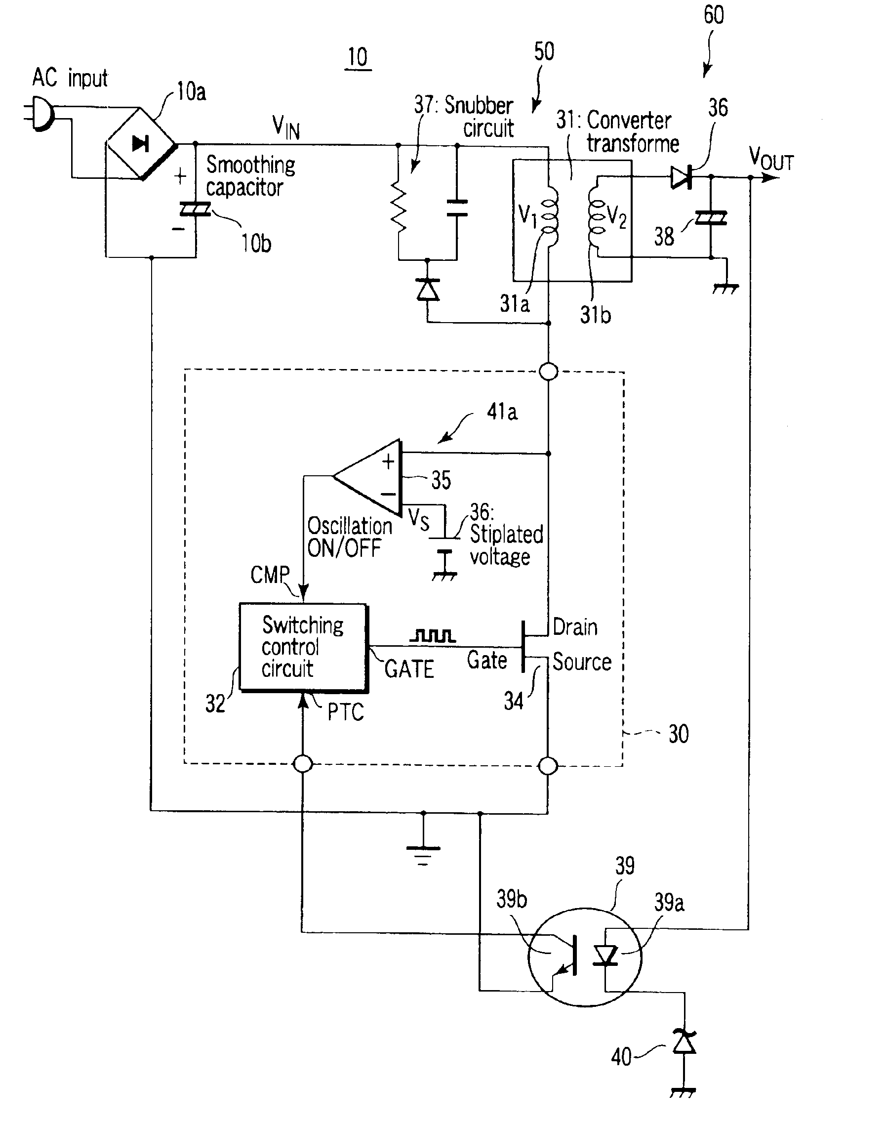
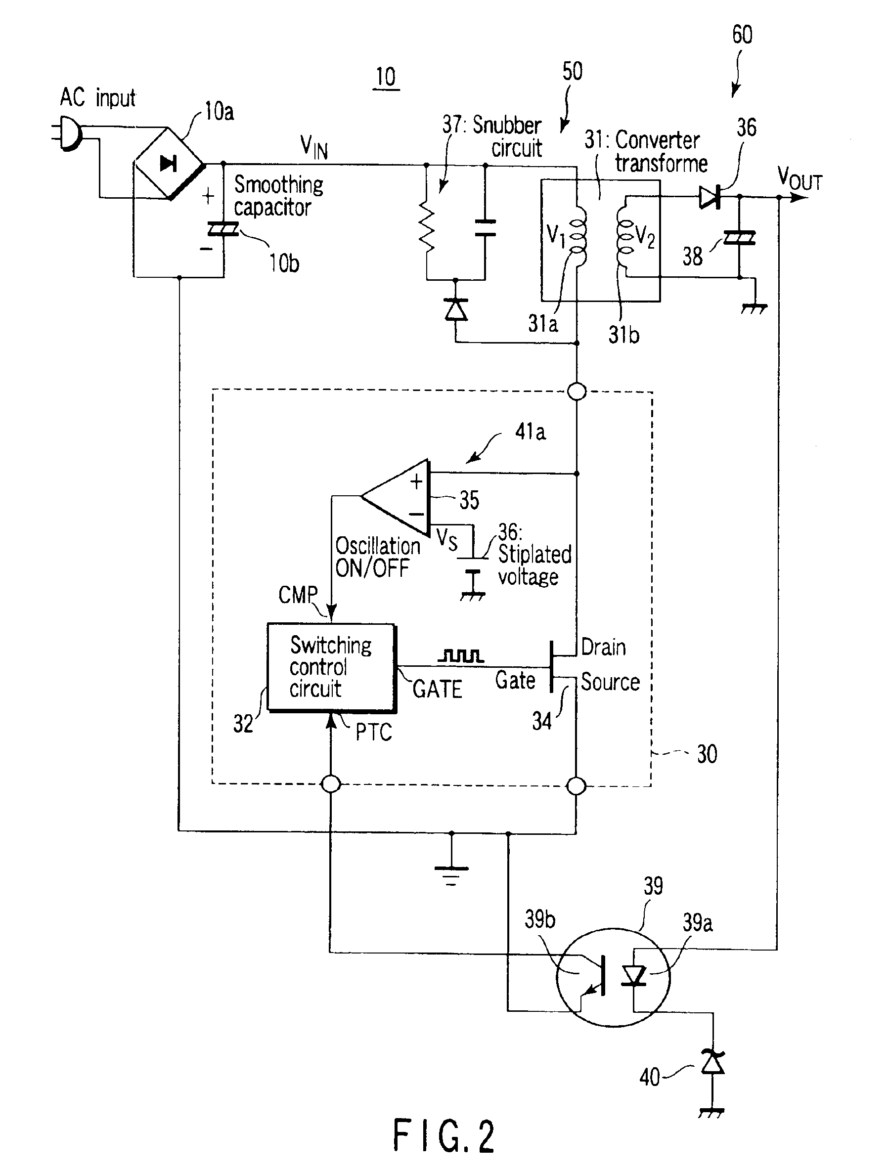
[0031]FIG. 2 is a circuit diagram illustrating the standby power supply circuit 10, according to the invention, employed in the above-described electronic device.

[0032]The standby power supply circuit 10 comprises an input-side power supply circuit 50 and output-side power supply circuit 60. The input-side power supply circuit 50 has a rectifier circuit 10a for rectifying an AC voltage from a commercial power supply (AC input), and a smoothing capacitor 10b for smoothing the output voltage of the rectifier circuit 10a. The DC input voltage VIN generated across the smoothing capacitor 10 is applied to an end of the primary winding 31a of a converter transformer 31.

[0033]The other end of the primary winding 31a of the converter transformer 31 is connected to the drain of a MOSFET (hereinafter referred to simply as a “FET”) 34 functioning as a switching element. The gate of the FET 34 is connected to the GATE terminal of a switching control circuit 32 so that the switching operation of...

third embodiment

[0053]FIGS. 6 and 7 show voltage detection circuits 44 according to the invention. In the example shown in FIG. 6, a low voltage detection circuit 41d is provided as well as the surge voltage detection circuit 41a. The low voltage detection circuit 41d comprises a comparator 43 having a non-inverting input terminal to which a voltage VL is input, and an inverting input terminal to which the input DC voltage VIN is input. The output of the comparator 35 is connected to a terminal CMP1 of the switching control circuit 32, while the output of the comparator 43 is connected to the other terminal CMP2 of the circuit 32. In this embodiment, if the AC input power supply voltage is within a predetermined voltage range, the standby power supply is turned on to thereby turn on the main power supply switch 12.

[0054]Specifically, the input power supply voltage range for the standby power supply circuit can be easily widened since the output power of the standby power supply circuit is low. For ...

fourth embodiment

[0057]Further, FIG. 8 illustrates a surge voltage detection circuit 41f according to the invention. A diode 45, resistor R4 and capacitor 46 form a peak hold circuit. The comparator 35 compares the voltage held by the peak hold circuit with a third stipulated voltage VS2 generated by a third stipulated voltage generating section 47.

[0058]The surge voltage detection circuit 41f detects whether or not the momentary peak value of the drain voltage VD shown in FIG. 3 is higher than the third stipulated voltage. Accordingly, in this embodiment, the maximum drain voltage of the switching element FET 34, when the standby power supply circuit 10 is performing a switching operation, is detected, in addition to the drain voltage upon turn-on of the electronic device (before oscillation is started). Thus, oscillation is stopped before the maximum drain voltage exceeds the breakdown voltage of the FET 34.


PUM


Abstract

A surge voltage detection circuit compares a stipulated voltage VS with the drain voltage of a switching element, the drain voltage being applied by a smoothing capacitor. The comparison result is supplied to a switching control circuit. If the drain voltage of the switching element is higher than the stipulated voltage VS, the switching control circuit inhibits the operation of the switching element. As a result, no switching operation is started, and the drain voltage of the switching element does not exceed the breakdown voltage of the element.

Description

CROSS-REFERENCE TO RELATED APPLICATIONS[0001]This application is based upon and claims the benefit of priority from the prior Japanese Patent Application No. 2002-175612, filed Jun. 17, 2002, the entire contents of which are incorporated herein by reference.BACKGROUND OF THE INVENTION[0002]1. Field of the Invention[0003]The present invention relates to a switching power supply circuit for converting an AC power supply voltage to a DC power supply voltage, and more particularly to a switching power supply circuit preferably used as a standby power supply circuit and capable of protecting a switching element from a surge voltage.[0004]2. Description of the Related Art[0005]Most electronic devices, such as television sets, are provided with a main power supply circuit for operating each element in the main unit, and a standby power supply circuit for continuously operating standby circuits, such as a light receiving circuit for receiving a signal from a remote controller, a microcomput...

Claims


Application Information

Patent Timeline
IPC IPC(8): H02M1/00H02M3/335H02M3/24H02M3/28
CPCH02M3/33507H02M1/32H02M1/36
Inventor HIROSAWA, HIDEKI
Owner KK TOSHIBA
Why Eureka
Try Eureka