
Apparatus and method for creating signal and profiles at a receiving station

Active Publication Date: 2005-09-20
RAZE TECH
View PDF14 Cites 6 Cited by
  • Summary
  • Abstract
  • Description
  • Claims
  • Application Information

AI Technical Summary

Benefits of technology

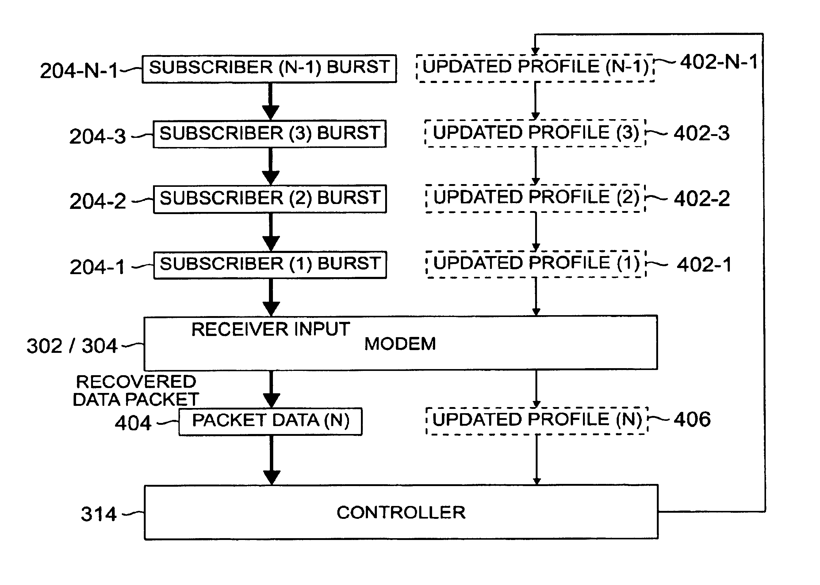
[0061]Through operation of an embodiment of the present invention, an increase in the speed and accuracy by which bursts of burst data signals are operated upon, when received at the receiving station, is possible.
[0065]During operation of an embodiment of the present invention, data signals are processed at a receiving station, such as a base station in a fixed wireless access communication system. The data signals are transmitted to the receiving stations by any of a plurality of subscriber stations. Improved uplink capacity of data signals sent by the subscriber stations to the base station is possible as a result of operation of an embodiment of the present invention. Additionally, better compensation is made to counteract the effects of distortion of the data signals communicated during operation of a communication system in which an embodiment of the present invention is implemented.
[0068]In these and other aspects, therefore, profile-creating apparatus and an associated method, is provided for creating at least a first profile associated with at least a first channel. At least a first burst data signal is transmitted in bursts upon the at least the first channel to a receiving station. A profile parameter determiner is coupled to receive an indication of an initial burst of the first burst data signal transmitted upon the first channel to the receiving station. The profile parameter determiner determines a value of at least one parameter representative of communication of the burst data signal to the receiving station. A profile parameter storage device is coupled to the profile parameter determiner. The profile parameter storage device stores values representative of the at least one parameter determined by the profile parameter determiner. The values stored at the profile parameter storage device are used to facilitate receive operations performed at the receiving station of subsequent bursts of the first burst data signal.

Problems solved by technology

By the late 1980s, the limitations of data modem connections over voice frequency (VF) pairs were becoming obvious to both subscribers and telecommunications service providers.
However, the rollout in the United States was not successful, due in part to artificially high tariff costs which greatly inhibited the acceptance of ISDN.
The cost of providing a wired connection to a small percentage of rural subscribers was high enough to justify the development and expense of small-capacity wireless local loop (WLL) systems.
Also, it is more economically feasible to install FWA systems in developing countries where the market penetration is limited (i.e., the number and density of users who can afford to pay for services is limited to small percent of the population) and the rollout of wired infrastructure cannot be performed profitably.
However, in many areas, the cost of cable modem or DSL service is high.
Additionally, data rates may be slow or coverage incomplete due to line lengths.
In these areas and in areas where the high cost of replacing old telephone equipment or the low density of subscribers makes it economically unfeasible to introduce either DSL or cable modem broadband access, fixed wireless broadband systems offer a viable alternative.
Unfortunately, the diversity of broadband access technology has resulted in a lack of standardization in the broadband access equipment.
Cable modems and DSL routers are incompatible with each other and with fiber optic equipment.
Often this equipment is located inside the office or residence of the subscriber, which makes it inaccessible to maintenance workers unless the subscriber is present to admit the workers to the premises.
The lack of standardization of broadband access equipment and the frequent inaccessibility of such equipment adds to the cost and complexity of broadband access.

Method used


Image

  • Apparatus and method for creating signal and profiles at a receiving station
  • Apparatus and method for creating signal and profiles at a receiving station
  • Apparatus and method for creating signal and profiles at a receiving station

Examples


Embodiment Construction

[0076]FIGS. 1 through 5, discussed below, and the various embodiments used to describe the principles of the present invention in this patent document are by way of illustration only and should not be construed in any way to limit the scope of the invention. Those skilled in the art will understand that the principles of the present invention may be implemented in any suitably arranged subscriber integrated access device.

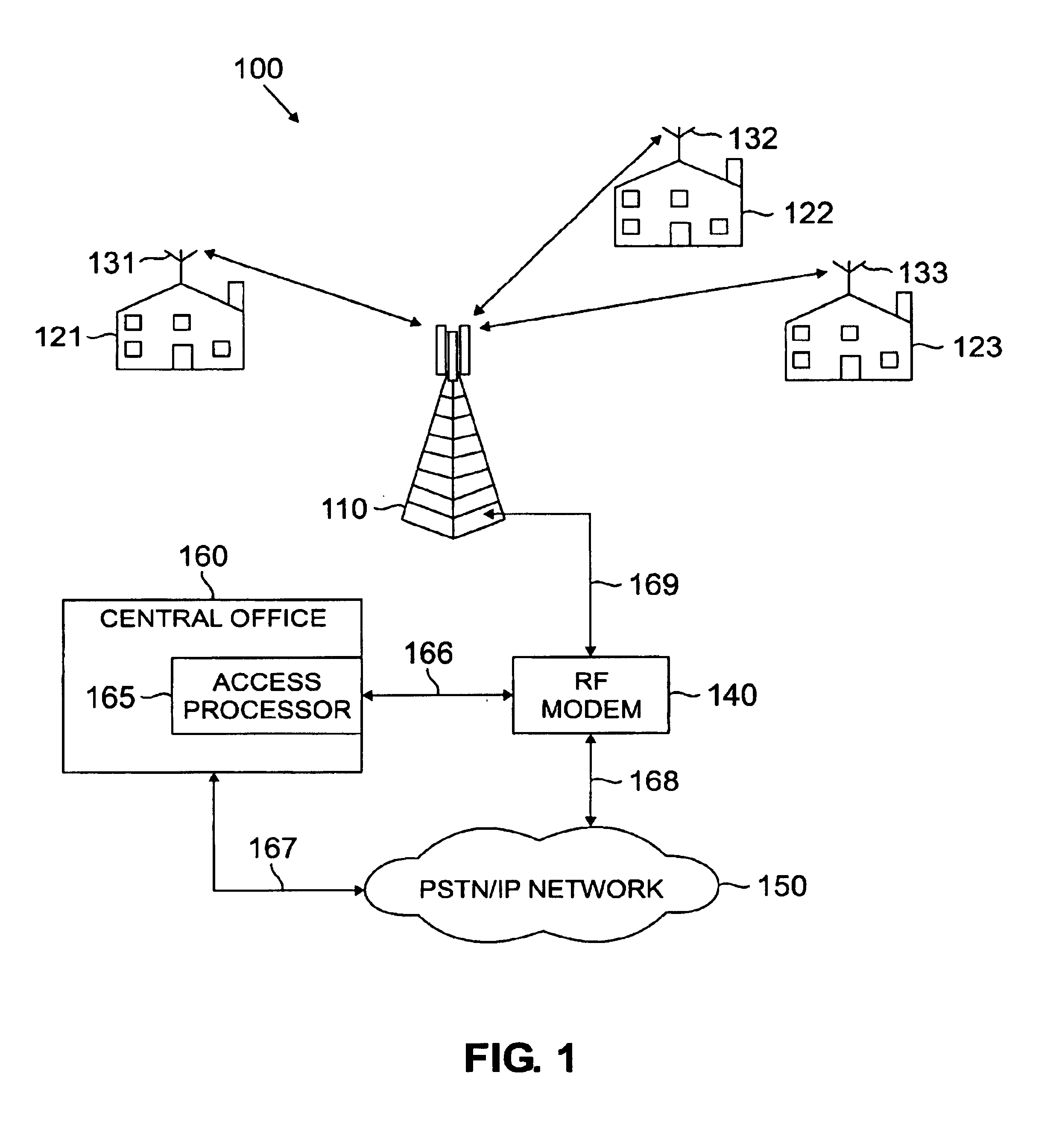
[0077]FIG. 1 illustrates exemplary fixed wireless access network 100 according to one embodiment of the present invention. Fixed wireless network 100 comprises a plurality of transceiver base stations, including exemplary transceiver base station 110, that transmit forward channel (i.e., downlink or downstream) broadband signals to a plurality of subscriber premises, including exemplary subscriber premises 121, 122 and 123, and receive reverse channel (i.e., uplink or upstream) broadband signals from the plurality of subscriber premises. Subscriber premises 121-123 ...


PUM


Abstract

Apparatus, and an associated method, for creating a profile associated with burst data signals communicated to a base station of a fixed wireless access communication system. The profile is created to facilitate receive operations performed upon subsequent bursts of the burst data signal. The profile is stored at a storage device and retrieved when subsequent bursts of the bursts data signal are received at the base station.

Description

CROSS-REFERENCE TO RELATED APPLICATIONS[0001]The present invention claims priority to U.S. Provisional Application Ser. No. 60 / 262,827 filed Jan. 19, 2001.[0002]The present invention is related to those disclosed in the following United States Provisional and Non-Provisional Patent Applications:[0003]1) Ser. No. 09 / 713,684, filed on Nov. 15, 2000, entitled “SUBSCRIBER INTEGRATED ACCESS DEVICE FOR USE IN WIRELESS AND WIRELINE ACCESS SYSTEMS”;[0004]2) Ser. No. 09 / 838,810, filed Apr. 20, 2001, entitled “WIRELESS COMMUNICATION SYSTEM USING BLOCK FILTERING AND FAST EQUALIZATION-DEMODULATION AND METHOD OF OPERATION”;[0005]3) Ser. No. 09 / 839,726, filed Apr. 20, 2001, entitled “APPARATUS AND ASSOCIATED METHOD FOR OPERATING UPON DATA SIGNALS RECEIVED AT A RECEIVING STATION OF A FIXED WIRELESS ACCESS COMMUNICATION SYSTEM”;[0006]4) Ser. No. 09 / 839,729, filed Apr. 20, 2001, entitled “APPARATUS AND METHOD FOR OPERATING A SUBSCRIBER INTERFACE IN A FIXED WIRELESS SYSTEM”;[0007]5) Ser. No. 09 / 838,9...

Claims


Application Information

Patent Timeline
IPC IPC(8): H01Q1/24H04L27/26H04B7/02H04L12/56H04L12/10H04L1/00H04Q7/20H04L12/28H04M3/42H04L1/12H04L1/16H04Q7/22H04Q7/32H04Q7/38G06F1/00H01Q25/00H04B7/005H04J3/00H04J11/00H04L5/14H04L7/00H04L25/03H04M1/00H04W4/90H04W16/28H04W28/04H04W28/18H04W72/00H04W76/02H04W84/14H04W88/02H04W88/08H05K1/14
CPCH01Q1/246H04B7/022H04L1/0005H04L1/0009H04L1/0017H04L1/007H04L12/10H04L12/403H04L12/66H04L27/2647H04M3/42H04W16/28H04W88/021H04L1/0003H04L1/16H04L2001/0098H04L2001/125H04M2207/206H04M2242/04H04M2242/06H04W28/04H04W28/18H04W84/14H04W88/08
Inventor STRUHSAKER, PAUL F.MCKOWN, RUSSELL C.
Owner RAZE TECH
Learn More