
Optical cross-connect device

a cross-connecting device and optical technology, applied in the field of optical cross-connecting devices, can solve the problems of affecting reducing the service life of the device, so as to achieve high service life, simple structure, and low cost

Inactive Publication Date: 2005-09-20
PEGASUSNET
View PDF1 Cites 8 Cited by
  • Summary
  • Abstract
  • Description
  • Claims
  • Application Information

AI Technical Summary

Benefits of technology

"The present invention provides an optical cross-connect device and an optic switch that can meet the requirements of an ultra-large WDM transmission system. The device is simple in structure, requires no moving parts, and can operate at extremely high speeds. It can provide several thousand channels and can switch between them quickly. The device includes a multimode optical waveguide with electrode means and a holographic filter with pre-formed speckle patterns. The optical switch can selectively switch, address, and cross-connect input laser beams to output optical waveguides. The device can be preformed with holograms and the hologram can be created by applying different control voltages to the electrode pairs. The technical effects of the invention are to provide an efficient and reliable solution for ultra-large WDM transmission systems."

Problems solved by technology

However, this switch requiring the movement of a small mirror that must be rotated or vertically moved has a problem in durability.
It also has the problem that its switching speed is as low as requiring 50 milliseconds for switching.
On the other hand, the “mechanical type switch” is operable at a switching speed as relatively high as can be switched in 10 milliseconds or less, but has the problem that it can only provide several channels and hence cannot be utilized but for limited, small scale applications.
However, using the structure requiring that a groove filled with a heater or liquid be formed in a substrate, these switches have left more or less to be desired in durability.
Further, while no mechanical movement is required in these switches, they do require more or less mechanical components, presenting the problem that their structures become intricate.

Method used


Image

  • Optical cross-connect device
  • Optical cross-connect device
  • Optical cross-connect device

Examples


Embodiment Construction

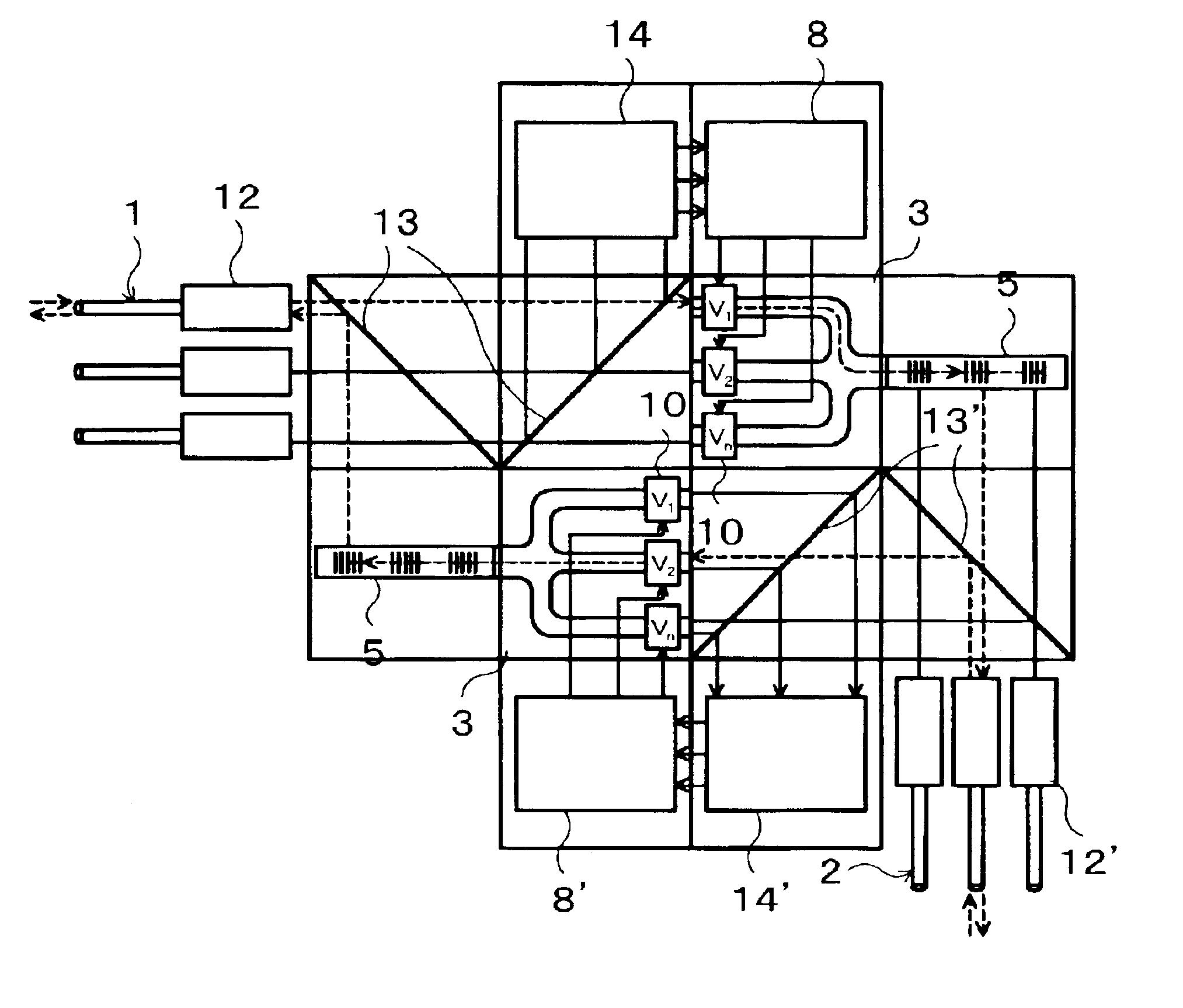
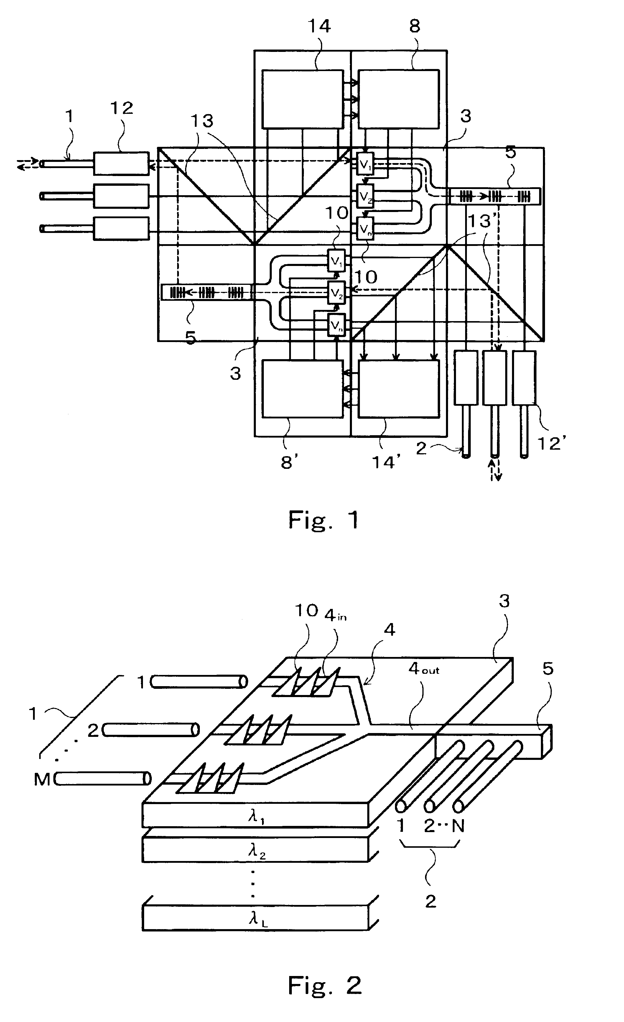
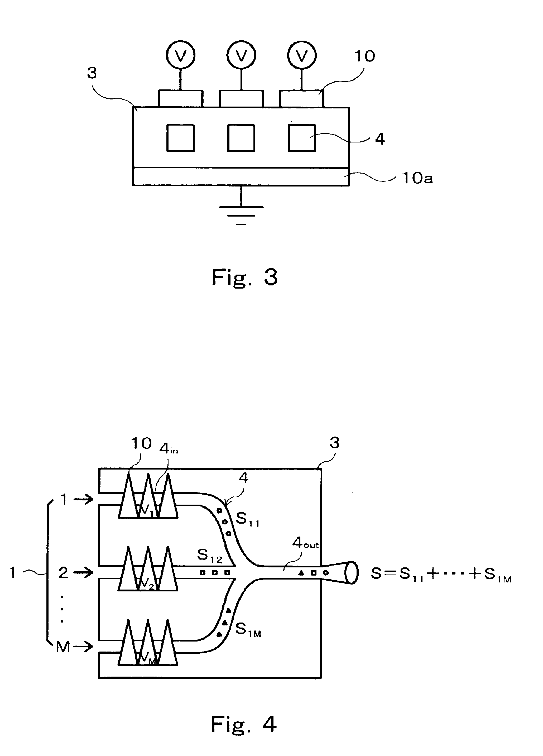
[0039]FIG. 1 is a general conceptual view of an optical cross-connect device according to the present invention, and FIG. 2 is a conceptual view of an optic switch in the optical cross-connect device of the invention for applying an electrooptical effect to a multimode optical waveguide. Referring to FIG. 1, mixed light signals carried on various wavelengths (λ1, λ2, . . . , λL) that are L in number are introduced, respectively, from an M number of input optical fibers 1, and are passed through an AWG (Arrayed Waveguide Grating) type coupler / divider (converter) 12, an array of such converters, where they are divided into L sets of light signals with each set having light signals which are M in number) and of an identical wavelength (λ1, λ2, . . . , λL). The M light signals for each of the L wavelengths then past a dichroic mirror 13 are guided into one of multimode optical waveguides 4 that are L in number. Each multimode optical waveguide 4 comprises its inlet passages 4in which ar...


PUM

PropertyMeasurementUnit
wavelengthaaaaaaaaaa
sizeaaaaaaaaaa
wavelengths λiaaaaaaaaaa

Abstract

An optic switch for cross-connecting input light signals incoming from inlet fiber cables to outlet fiber cables is disclosed that makes use of a holographic filter (5) having a series of preformed different speckle patterns, each in the form of a hologram (H1, H2, . . . ). Associated with input light signals guided past respective inlet passages (4in) of a multimode waveguide (4), different speckle patterns are formed by applying different control voltages across respective electrode pairs (10, 10a) provided thereon. These speckle patterns past a single outlet passage (4out) of the multimode waveguide (4) into which the inlet passages (4in) converge are joined together and enter the holographic filter (5) in which an input light signal is selectively switched, addressed and cross-connected to an outlet waveguide (2) through a region thereof where a formed speckle pattern coincides with a preformed speckle pattern. The multi mode waveguides (4) is formed in, e. g., a LiNbO3 photorefractive substrate (3).

Description

BACKGROUND OF THE INVENTION[0001]1. Field of the Invention[0002]The present invention relates to an optical cross-connect device that is capable of changing paths for optical signals, viz. switching, addressing and cross-connecting a plurality of input light signals to a plurality of outlet optical waveguides directly without converting the optical signals into electrical signals, in a WDM (Wavelength Division Multiplexing) transmission control apparatus that permits high-speed signal transmission in an optical backbone network.[0003]2. Description of the Prior Art[0004]With the tremendous spreads of personal computers and cellular phones for use to access Internet sites, high speed broadband communication services by xDSL and sustained connection options have come into wide use in the communication infrastructure as well. And, to harmonize with the next-generation Internet communication and the next-generation cellular phone a further drastic rise in the line speed in the backbone ...

Claims


Application Information

Patent Timeline
Patent Type & Authority Patents(United States)
IPC IPC(8): H04Q11/00G02B5/32G02F1/03G11C13/04
CPCG02B5/32G11C13/042H04Q11/0005G02B6/3556G02B6/356G02F1/0338H04Q2011/0028H04Q2011/0035H04Q2011/0039G02B26/08
Inventor SUGIYAMA, TERUYAINOUE, MITSUTERUDONG-HAK, SHINMASUDA, HITOSHI
Owner PEGASUSNET
Learn More