Apparatus and method of using supersonic combustion heater for hypersonic materials and propulsion testing

Inactive Publication Date: 2005-09-27
THE GOVERNMENT OF THE UNITED STATES OF AMERICA AS REPRESENTED BY THE SEC OF THE NAVY NAVAL RES LAB WASHINGTON
View PDF18 Cites 10 Cited by
  • Summary
  • Abstract
  • Description
  • Claims
  • Application Information

AI Technical Summary

Benefits of technology

[0016]The most preferred embodiment of the present invention is a method of using supersonic combustion to create a high enthalpy flow source for application in scramjets comprising the steps of: providing a heated high-pressure flow which is expanded through a first nozzle creating a supersonic duct flow having a boundary layer flow; generating coherent vortices using a resonant acoustic side wall cavity having a downstream lip which causes shedding of periodic coherent vortices downstream to enhance supersonic mixing rates and shorten mixing times while increasing combustion efficiency; injecting three fluid streams for rapid mixing including the duct flow, the fuel, and auxiliary oxygen; and pa

Problems solved by technology

Supersonic combustion is a very difficult subject that has been attacked often in the past with limited success.
It is mechanically simple having a burner (2), but vastly more complex aerodynamically than a jet engine.
Scramjet technology is challenging because only limited testing can be performed in ground facilities.
Without some means of controlling the burn rate of the solid fuel in response to changes in air mass flow excessively rich combustion chamber conditions will exist, which is very wasteful of fuel and reduces the range of the vehicle.
Combustion instability has been a problem of major concern.
Vortex shedding can lead to excessive thrust

Method used


Image

  • Apparatus and method of using supersonic combustion heater for hypersonic materials and propulsion testing
  • Apparatus and method of using supersonic combustion heater for hypersonic materials and propulsion testing
  • Apparatus and method of using supersonic combustion heater for hypersonic materials and propulsion testing

Examples


Example

EXAMPLE 1

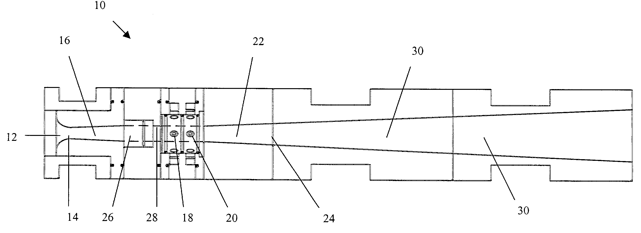
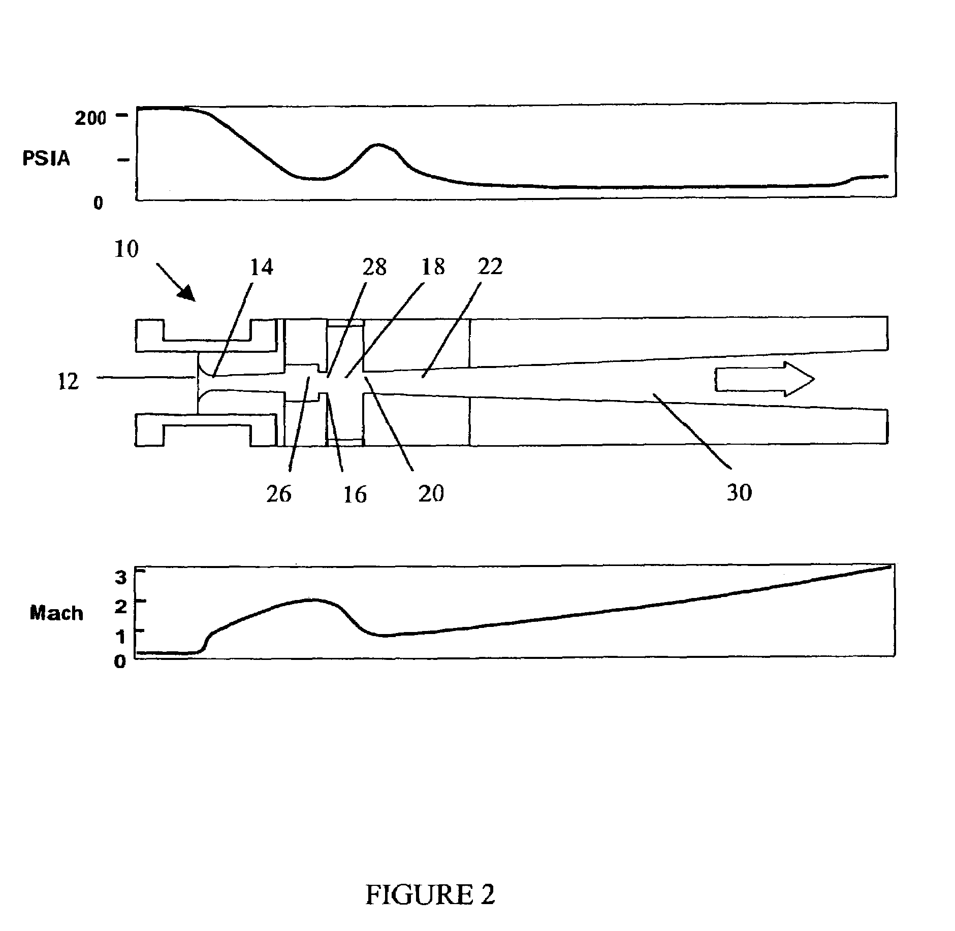
[0040]For testing purposes, the expansion zone or region 22 is instrumented with multiple static pressure probes (not shown). FIG. 2 illustrates schematic graphs showing the pressure (top) and Mach (bottom) scaled to the device 10 (partially from measurement, partially from calculation). The present invention 10 passed the testing of the materials and propulsion systems required for very high speed strike on time critical targets. Stable supersonic combustion was successfully achieved with the first design.

[0041]FIG. 3 shows the results of the static pressure probe profiles. Atmospheric conditions correspond to p / pt=0.072. The abscissa is the axial position with respect to the start of the expansion just downstream of the fuel injection station 18. It is scaled by the initial flow diameter (D1=16 mm). The ordinate is the static pressure scaled to the initial total pressure. The X's are the data for the non-reacting expansion and the solid line is the simulation of that case...


PUM


Abstract

A supersonic combustion apparatus and method of using the same including a side wall cavity having an enhanced mixing system with ground-based oxygen injection for hypersonic material and engine testing.

Description

STATEMENT REGARDING FEDERALLY SPONSORED RESEARCH OR DEVELOPMENT[0001]The invention described herein may be manufactured and used by or for the government of the United States of America for governmental purposes without the payment of any royalties thereon or therefor.FIELD OF THE INVENTION[0002]This invention relates to a supersonic combustion apparatus and method of using the same for hypersonic materials and propulsion testing, and more specifically, a supersonic heater having a cavity enhanced mixing system with ground-based oxygen injection for hypersonic material and engine testing.BACKGROUND OF THE INVENTION[0003]Hypersonic missiles have a future Naval need to reduce the time to impact on time critical targets. Supersonic combustion is a very difficult subject that has been attacked often in the past with limited success. Hypersonic missiles have utilized both ramjet and scramjet technologies and designs to reach both high speeds and long-range capabilities.[0004]FIG. 4A illu...

Claims


Application Information

Patent Timeline
IPC IPC(8): B64G9/00B63H11/00F02K9/00B64G1/40B64G1/58B64G7/00B64G99/00F02K7/10F02K7/14F23R5/00
CPCB64G7/00F02K7/10F02K7/14F23R5/00B64G1/401B64G1/58F05D2220/10F05D2250/52F05D2250/51
Inventor WILSON, KENNETH J.PARR, TIMOTHY P.YU, KENWARREN, JAUL
Owner THE GOVERNMENT OF THE UNITED STATES OF AMERICA AS REPRESENTED BY THE SEC OF THE NAVY NAVAL RES LAB WASHINGTON
Why Eureka
Try Eureka