Barrier discharge device

Inactive Publication Date: 2013-06-27
DAIHATSU MOTOR CO LTD
View PDF22 Cites 4 Cited by
  • Summary
  • Abstract
  • Description
  • Claims
  • Application Information

AI Technical Summary

Benefits of technology

The present invention offers a barrier discharge device that can improve engine combustion while addressing issues such as difficult electrode replacement and commercialization.

Problems solved by technology

However, since the peripheral electrodes have a structure where the peripheral electrodes protrude toward the combustion chamber, it is difficult to secure endurance reliability.
Hence, even when only one of the peripheral electrodes is consumed, there are drawbacks that all of the peripheral electrodes have to be replaced for each head gasket.
Further, while the peripheral electrodes disclosed in Patent Document 1 are held by ceramics and are fired, the sintering of ceramics is difficult to be carried out.
That is, it is difficult to sinter and fabricate the ceramics without hollows at a state where the metallic peripheral electrode is exposed, so that commercialization and mass production thereof cannot be easily achieved.
Further, there is also a problem that it is difficult to realize the commercialization because the electrodes are embedded into the head gasket.

Method used


Image

  • Barrier discharge device
  • Barrier discharge device
  • Barrier discharge device

Examples


Embodiment Construction

[0018]An illustrative embodiment of the present invention will now be described with reference to the accompanying drawings.

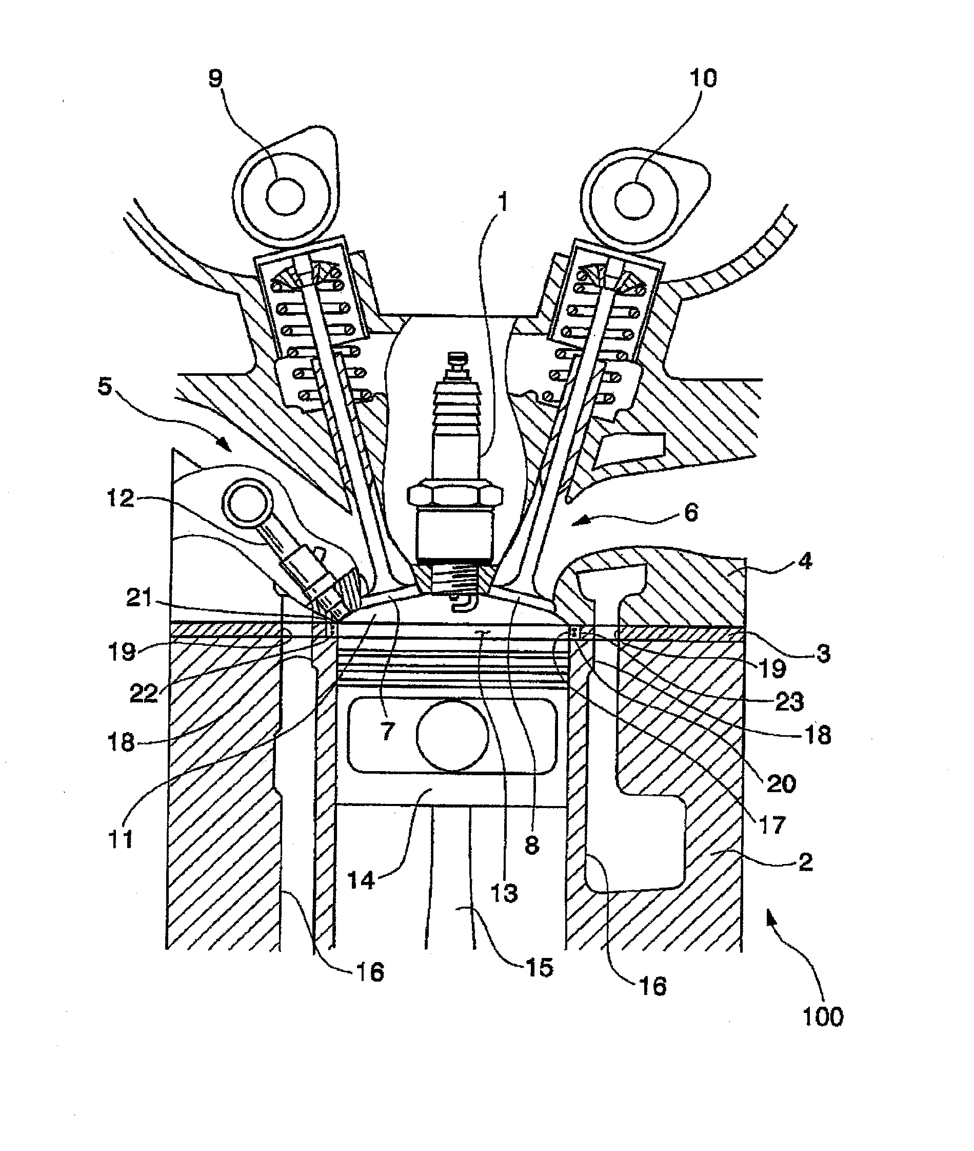
[0019]FIG. 1 illustrates a configuration of one cylinder of a 2-cylinder engine 100 that is a spark ignition internal combustion engine having an ignition plug 1. The engine 100 includes a cylinder block 2 having a cylinder and a cylinder head 4 which is attached to the cylinder block 2 with a head gasket 3 interposed therebetween. The cylinder head 4 is provided with an intake port 5 and an exhaust port 6, such that the intake port 5 and the exhaust port 6 are opened and closed by an intake valve 7 and an exhaust valve 8, respectively. The intake valve 7 is driven by an intake cam shaft 9 which is rotatably attached to the cylinder head 4, and the exhaust valve 8 is similarly driven by an exhaust cam shaft 10. The cylinder head 4 is also provided with a combustion chamber 11, in which the ignition plug 1 is attached at the center of the ceiling thereof, and a ...


PUM


Abstract

An object of the present invention is to provide a barrier discharge device capable of increasing the combustion efficiency of an engine while overcoming the problems of the cumbersome replacement of the electrodes and the commercialization of the device.The barrier discharge device of an engine includes a dielectric body and at least two barrier discharge electrodes which are held inside the dielectric body and to which voltages for barrier discharge are applied, wherein each of the barrier discharge electrodes are not exposed to the inside of a cylinder bore and are arranged so as to surround the cylinder bore.

Description

TECHNICAL FIELD[0001]The invention relates to a barrier discharge device for use in an engine, which includes a dielectric body and a barrier discharge electrode.BACKGROUND ART[0002]Conventionally, in the case of, for example, a spark ignition engine, a structure has been known in which multipoint ignition electrodes (hereinafter referred to as “peripheral electrodes”) are embedded into a head gasket which is disposed between a cylinder head and a cylinder block in order to obtain larger flames than only using a single ignition gap (see, for example, Patent Document 1).[0003]In such a structure, flames spread both concentrically and three-dimensionally in a combustion chamber from a central ignition plug arranged at the center of a ceiling of the combustion chamber and a plurality of peripheral electrodes. Accordingly, the time required for the flames to spread over the entire space of the combustion chamber is shortened, resulting in less time-loss and approaching a theoretical cyc...

Claims


Application Information

Patent Timeline
IPC IPC(8): F02P15/08F02P13/00
CPCF02F11/002F02P15/08F02P13/00F02P3/01F02M27/04F16J2015/0856H01T13/22H01T13/52
Inventor KIM, YOONHOSERIZAWA, TAKESHIOI, HIROAKINAKAJIMA, AKIRA
Owner DAIHATSU MOTOR CO LTD
Why Eureka
Try Eureka