Curette with detachable tip

a curette and tip technology, applied in the field of curettes, can solve the problems of reducing the useful life of the working tool member, increasing the overall cost of the tool, and requiring a large amount of manufacturing, so as to achieve the effect of reducing the cost of replacement, reducing the cost of manufacturing, and being easy to apply

Inactive Publication Date: 2005-09-27
HOLMED
View PDF9 Cites 50 Cited by
  • Summary
  • Abstract
  • Description
  • Claims
  • Application Information

AI Technical Summary

Benefits of technology

[0011]The shaft and tip are relatively inexpensive to manufacture. Further, a titanium nitrate coating may be readily applied to only the tip before assembly of the tool member. The coating operation is thus relatively inexpensive to perform when compared to coating operation

Problems solved by technology

The one-piece and welded working tool members are relatively expensive to manufacture.
Further, when the tip becomes worn, the entire member must be replaced, thus adding to the overall cost of the tool.
Also, the welded tool member may be damaged by excess heat during welding, which results in a softening of the material of the shaft a

Method used


Image

  • Curette with detachable tip
  • Curette with detachable tip
  • Curette with detachable tip

Examples


Embodiment Construction

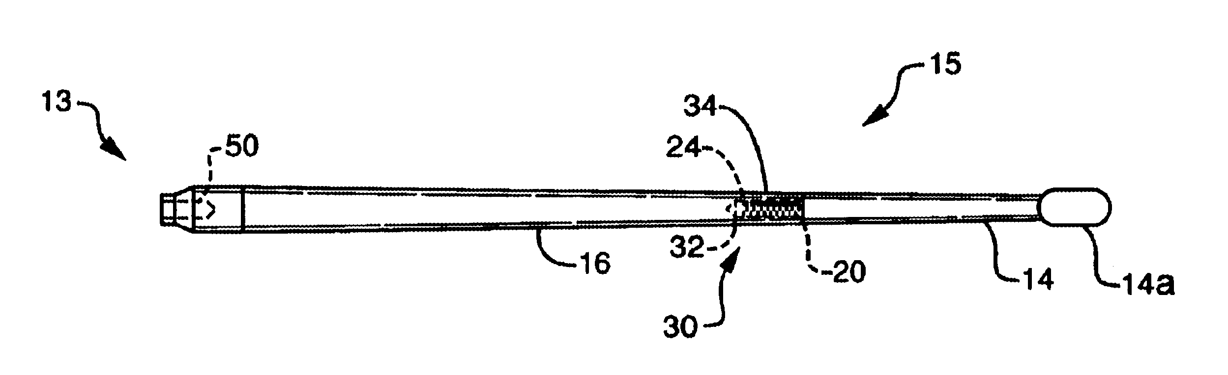
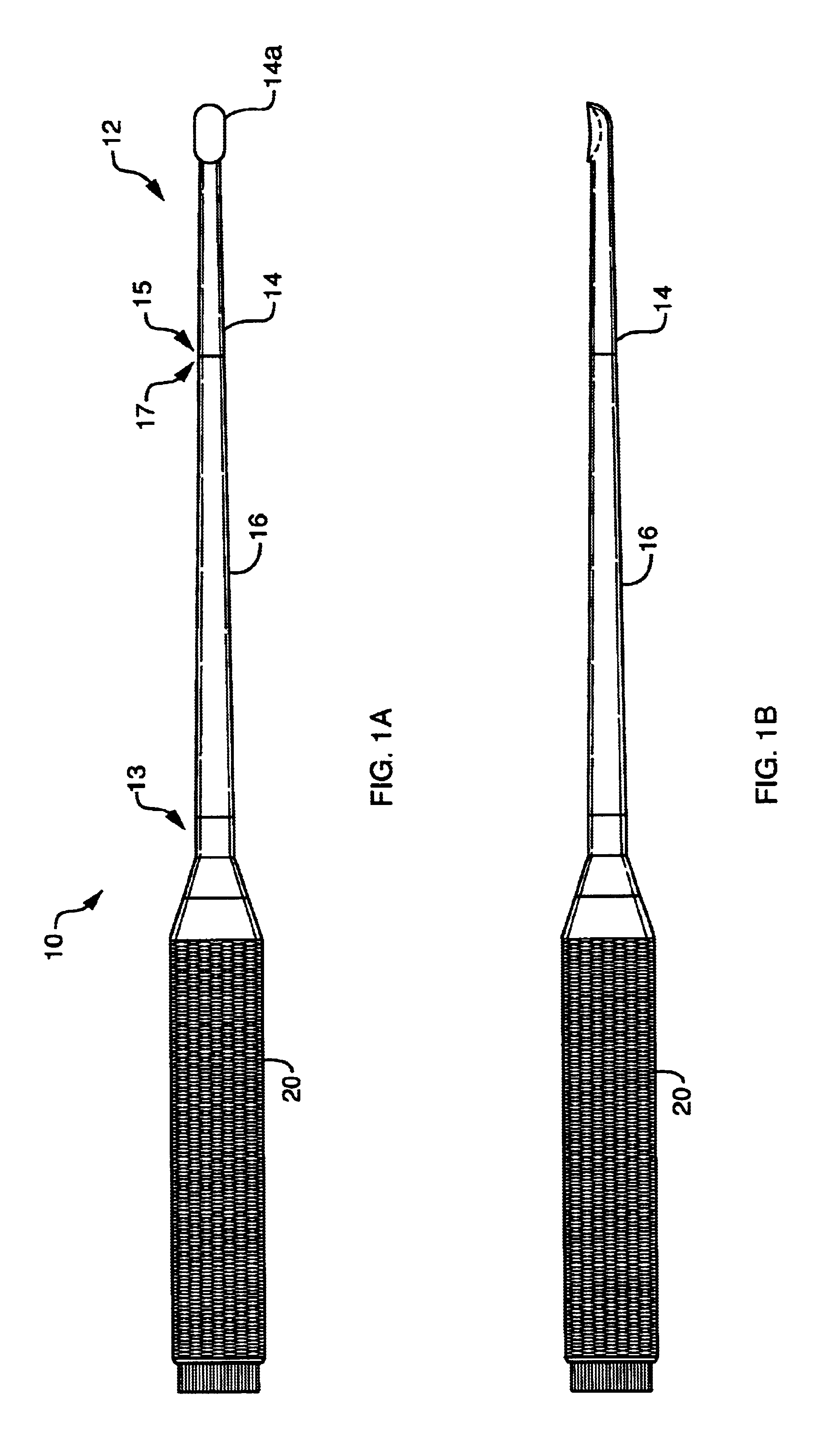
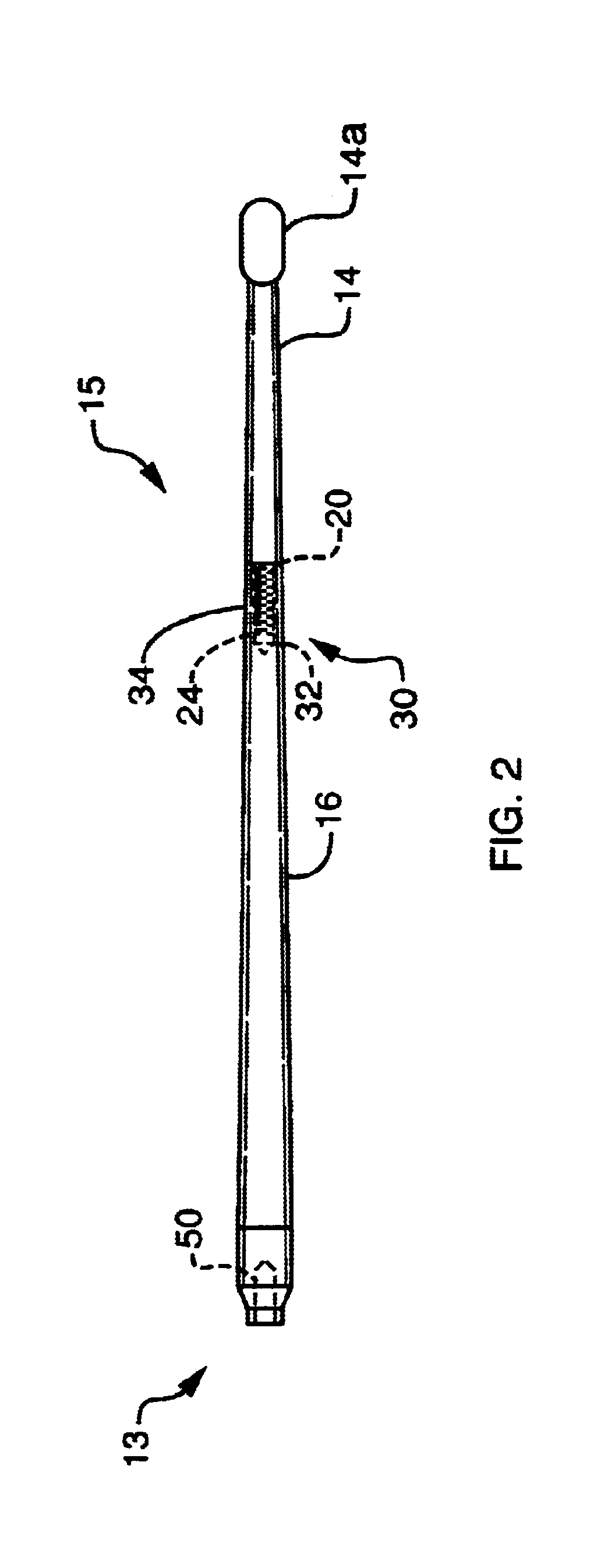
[0017]Referring to FIG. 1, a curette 10 includes a working tool member 12 that consists of a detachable tip 14 and a shaft 16. The tip 14 and shaft 16 connect together at mating ends 15 and 17, and a handle 20 detachably or permanently attaches to an opposite, or proximal, end 13 of the working tool member 12. The tip 14 may have a working end 14a that is shaped as a scoop, as shown in FIG. 2. Alternatively, the working end 14a may have various other shapes that are common to curettes, some of which are depicted in FIGS. 3 and 5.

[0018]Referring also to FIGS. 2-5, the mating end 15 of the tip 14 includes a threaded section 20 and an elongated end 24 that is flattened on at least one side 26. The elongated end may also may be flattened on additional sides 26, as depicted in FIG. 5. Preferably, there is a slight gap between the threads 22 and the start of the flattened portions 26 which extend to the outer end of the section 24. The mating, or distal, end 17 of the shaft 16 includes a ...


PUM


Abstract

The invention is a curette that includes a tip and shaft that detachably join together to form a working tool member. The shaft has a threaded receiving end that is sized to receive a mating end of the tip. The mating, or proximal, end of the tip includes a corresponding threaded section and a smaller-diameter outwardly extending elongated section that is flattened on one or more sides. To attach the tip to the shaft, a user partially fills the receiving end of the shaft with epoxy. The user then inserts the mating end of the tip into the receiving end of the shaft, such that the epoxy surrounds the elongated section of the mating end and fills or partially fills the threads. The user then screws the tip and shaft together, to interlock, or self-lock, the threads. When the epoxy thereafter hardens, the tip is firmly held against rotation relative to the shaft both by the epoxied and interlocked threads and the flattened-sided section that, because of its shape, resists rotation within the hardened epoxy. When the tip needs replacing, the tip is detached from the shaft by applying moderate heat to soften the epoxy and, thereafter, unscrewing the locking threads.

Description

CROSS-REFERENCE TO RELATED APPLICATIONS[0001]The present application claims the benefit of U.S. Provisional patent application Ser. No. 60 / 272,173, which was filed on Feb. 28, 2001, by Russell P. Holmes for an IMPROVED CURETTE and is hereby incorporated by reference.BACKGROUND OF THE INVENTION[0002]1. Field of the Invention[0003]The invention relates generally to curettes for use in surgical procedures.[0004]2. Background Information[0005]Curettes are used in surgical operations as scraping tools. The curette consists of a handle and a working tool member that includes an elongated shaft and a shaped tip, such as a scoop or ring. The tip has a sharpened edge that facilitates the scraping. For added durability, the working tool member may be coated with a durable coating, such as titanium nitrate.[0006]The working tool member is generally constructed either as a one piece member or with the tip and shaft permanently welded together. The handle permanently or detachably joins to a pro...

Claims


Application Information

Patent Timeline
IPC IPC(8): A61B17/22A61B17/00
CPCA61B17/320708A61B2017/00473
Inventor HOLMES, RUSSELL P.
Owner HOLMED
Why Eureka
Try Eureka