Dual substrate loadlock process equipment

a technology of process equipment and loadlocking, which is applied in the direction of charge manipulation, instruments, furniture, etc., can solve the problems of large glass substrates, difficult to transfer from position to position within the processing system, and large glass substrates, etc., to achieve compact size

Inactive Publication Date: 2005-09-27
APPLIED MATERIALS INC
View PDF156 Cites 74 Cited by
  • Summary
  • Abstract
  • Description
  • Claims
  • Application Information

AI Technical Summary

Problems solved by technology

Such glass substrates, however, are often larger than typical silicon wafers.
The use of large glass substrates introduces complexities into processing that may not be present when processing other types of substrates.
The large size and shape of glass substrates can make them difficult to transfer from position to position within a processing system when compared with smaller, circular-shaped substrates.
The need for larger chamber sizes to handle large substrates, as well as the use of large substrate cassettes in the loadlock, also leads to a requirement for larger and more powerful vacuum pumps, power supplies, control mechanisms and the like and a corresponding increase in system cost.
In particular, glass generally has a relatively low thermal conductivity, which can make it more difficult to uniformly heat and cool the substrate.
Temperature gradients may occur across the glass substrate, which can lead to undesirable stresses in the substrate upon cooling.
Temperature gradients during processing can also result in the components formed on the substrate surface having non-uniform electrical (and structural) characteristics.
As the system components become larger in size, these steps may be slowed even more due to the longer time it generally takes to heat and cool large components in a large volume chamber.
These slow operations tend to lower the system throughput.

Method used


Image

  • Dual substrate loadlock process equipment
  • Dual substrate loadlock process equipment
  • Dual substrate loadlock process equipment

Examples


Embodiment Construction

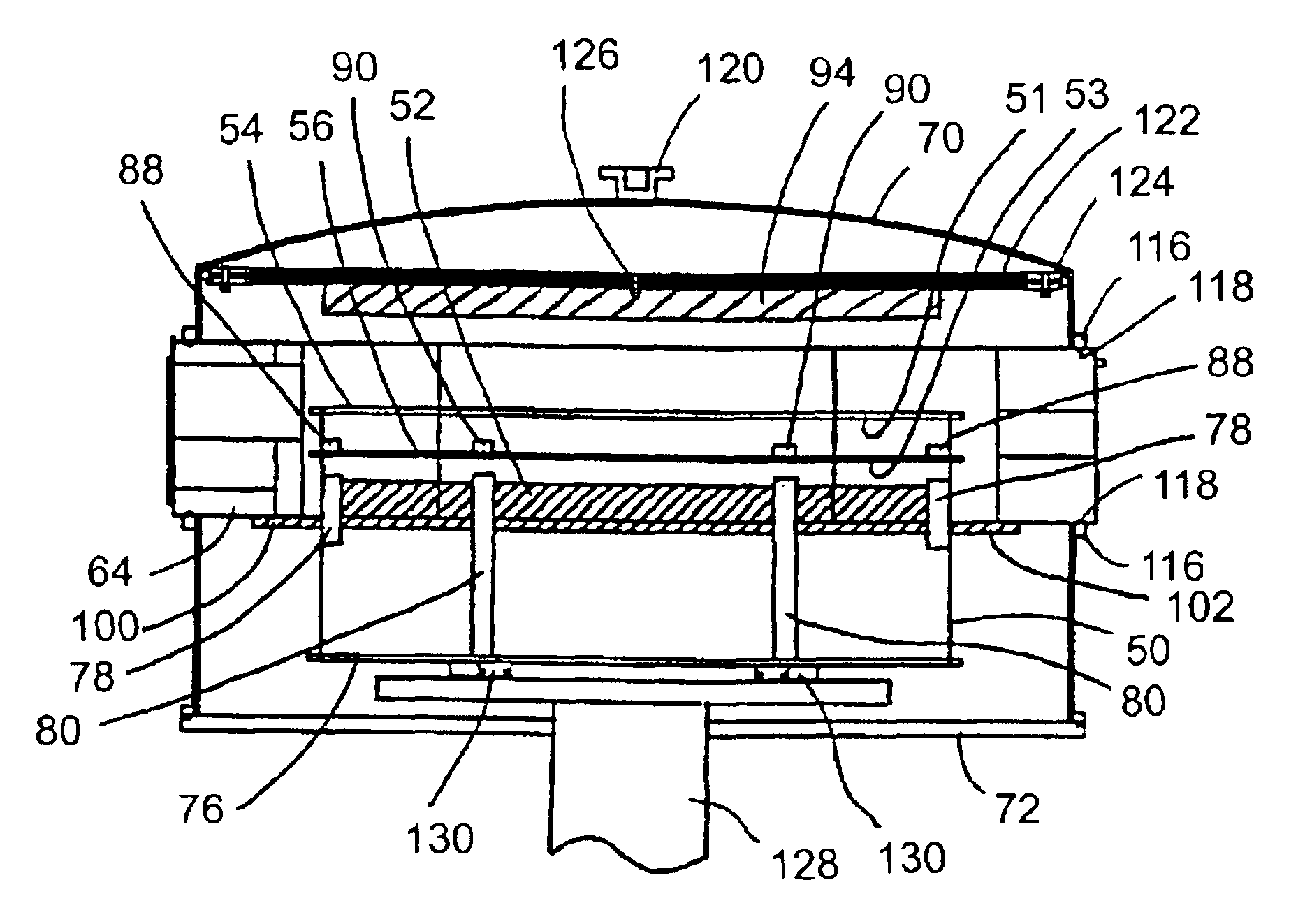
[0005]Certain embodiments of the present invention relate to loadlock devices for use in substrate processing systems that are relatively compact in size and that can achieve substrate transfer, cooling and / or heating operations in an efficient manner.

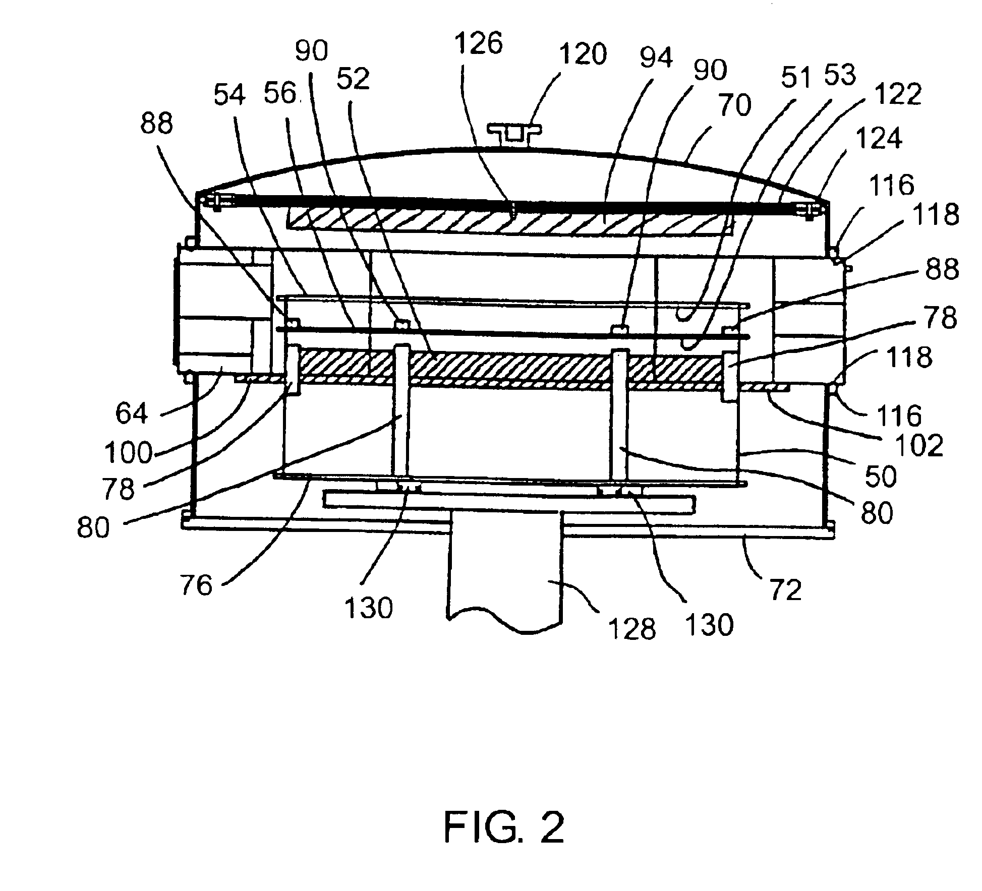
[0006]One embodiment relates to a loadlock having a first support structure adapted to support a first substrate and a cooling plate adapted to support a second substrate.

[0007]Another embodiment relates to a loadlock having a first support structure to support one unprocessed substrate and a second support structure to support one processed substrate. The first support structure is located above the second support structure and an elevator is provided to control the vertical position of the support structures. The loadlock also includes a first aperture to permit insertion of an unprocessed substrate into the loadlock and removal of a processed substrate from the loadlock, as well as a second aperture to permit removal of an unprocess...


PUM

PropertyMeasurementUnit
widthaaaaaaaaaa
widthaaaaaaaaaa
partial pressureaaaaaaaaaa

Abstract

One embodiment relates to a loadlock having a first support structure therein to support one unprocessed substrate and a second support structure therein to support one processed substrate. The first support structure is located above the second support structure. The loadlock includes an elevator to control the vertical position of the support structures. The loadlock also includes a first aperture to permit insertion of an unprocessed substrate into the loadlock and removal of a processed substrate from the loadlock, as wall as a second aperture to permit removal of an unprocessed substrate from the loadlock and insertion of a processed substrate into the loadlock. A cooling plate is also located in the loadlock. The cooling plate includes a surface adapted to support a processed substrate thereon. A heating device may be located in the loadlock above the first support structure.

Description

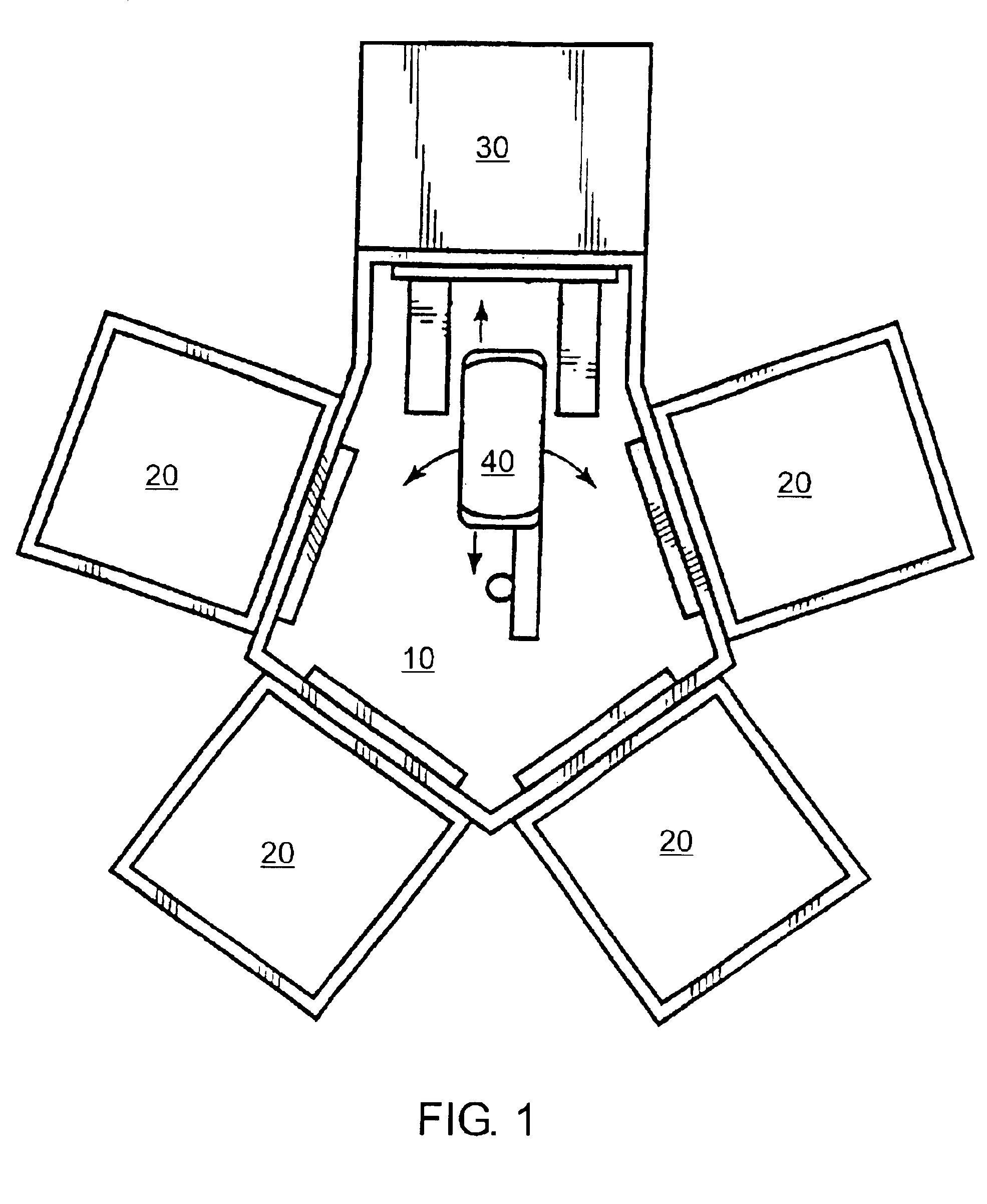
FIELD OF THE INVENTION[0001]The present invention relates to substrate processing systems, and, more particularly, to loadlock systems for handling substrates.BACKGROUND OF THE INVENTION[0002]Substrates such as, for example, glass panels used in applications such as television and computer displays may be fabricated using sequential steps including physical vapor deposition (PVD), chemical vapor deposition (CVD), etching, and annealing to produce the desired device. These steps may be carried out using a variety of processing systems having multiple chambers. One such system is known as a “cluster tool”. A cluster tool generally includes a central wafer handling module or transfer chamber and a number of peripheral chambers including a loadlock chamber through which workpieces are introduced into and removed from the system and a plurality of other chambers for carrying out processing steps such as heating, etching, and deposition. The cluster tool also generally includes a robot fo...

Claims


Application Information

Patent Timeline
Patent Type & Authority Patents(United States)
IPC IPC(8): B65G49/06B65G49/05H01L21/67H01L21/687H01L21/677H01L21/00G02F1/13C23C14/56C23C16/44H01L21/205H01L21/302H01L21/3065
CPCB65G49/068C23C14/566C23C14/568C23C16/54H01L21/67103H01L21/67109H01L21/67167H01L21/67201H01L21/67739H01L21/67745H01L21/67748H01L21/68742B65G2249/02B65G2249/04G02F1/13
Inventor KURITA, SHINICHIBLONIGAN, WENDELL T.HOSOKAWA, AKIHIRO
Owner APPLIED MATERIALS INC
Why Eureka
Try Eureka