Microfluidic control using dielectric pumping

a technology of dielectric pumping and microfluidics, which is applied in the direction of diaphragms, electrostatic separators, electrolysis, etc., can solve the problems of fluid movement and large pressure differentials, and achieve the effect of high performance and superior reliability

Inactive Publication Date: 2005-09-27
NEOPHOTONICS CORP
View PDF38 Cites 205 Cited by
  • Summary
  • Abstract
  • Description
  • Claims
  • Application Information

AI Technical Summary

Benefits of technology

[0015]Devices of the invention may be configured to be compatible with modem methods of fabricating devices such as microelectromechanical systems (MEMS), microarrays of genes, and electronics equipment. These include such methods as reactive ion etching, wet etching, micromachining, lithography (photo and X-ray), sputter deposition of materials, chemical vapor deposition (CVD) of materials including plasma-enhanced CVD and low-pressure CVD, and thus such devices can provide high-performance operation and superior reliability. Certain devices of the invention may also be made by other methods such as injection molding or embossing of polymers.

Problems solved by technology

However, the miniaturization of channels introduces problems of fluid movement where capillary forces predominate.
In microfluidic channels such as capillaries, however, large pressure differentials are needed to overcome the large flow resistance encountered in channels of such small cross-sectional area.

Method used


Image

  • Microfluidic control using dielectric pumping
  • Microfluidic control using dielectric pumping
  • Microfluidic control using dielectric pumping

Examples


Embodiment Construction

[0040]Several embodiments are discussed below and with reference to the attached drawings. These descriptions and drawings provide examples of certain embodiments of the invention and are not to be construed as limiting the scope of the invention. Instead, the invention is to be accorded the breadth as described herein and as defined in the claims that form part of this specification.

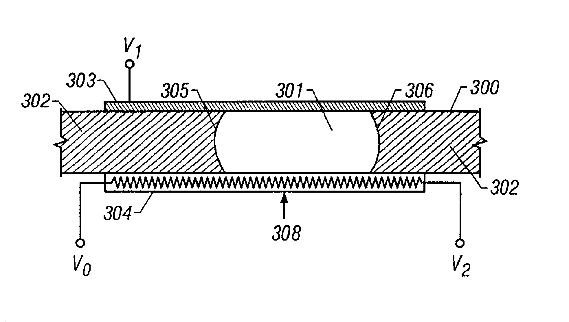
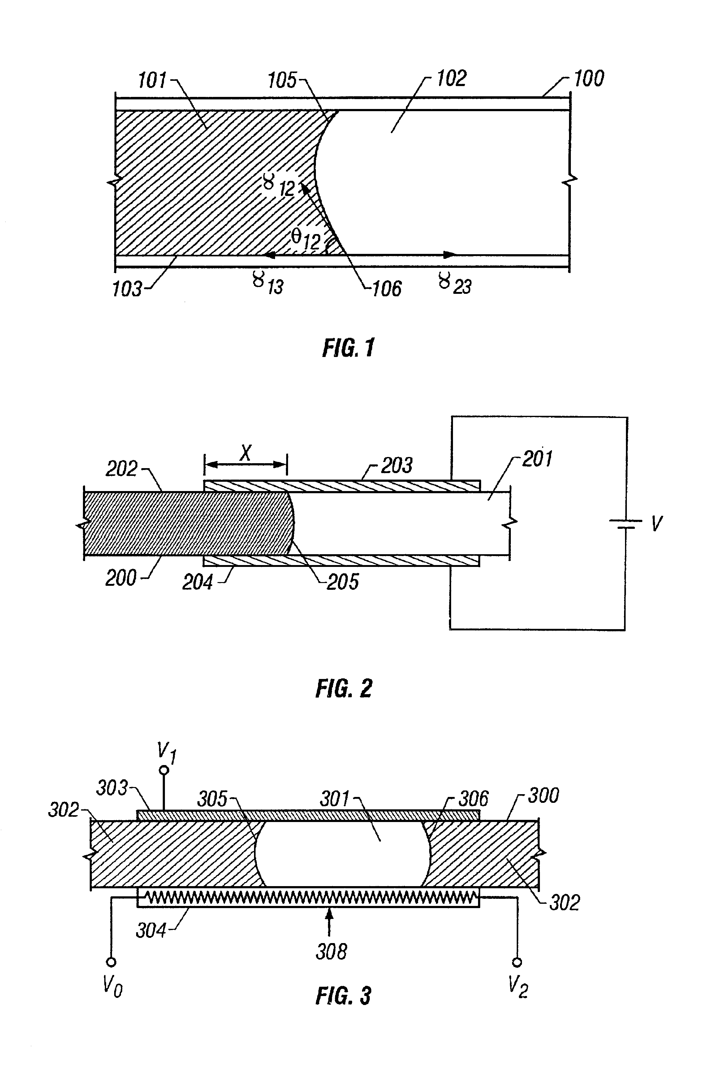
[0041]One factor in the operation of devices according to this invention is the ability to displace small volumes of liquid, in some cases only a few picoliters, in response to an electrical signal. Fluids can be moved by dielectric pumping or variable dielectric pumping, in which a difference in capacitance is used to move two dielectric fluids in contact with one another. Moving the fluid or fluids according to the principles disclosed herein can provide the low power dissipation and the material versatility sought of a preferred embodiment of this invention.

[0042]Following is a detailed description o...


PUM

PropertyMeasurementUnit
depthaaaaaaaaaa
widthaaaaaaaaaa
radiusaaaaaaaaaa

Abstract

Devices and methods utilizing dielectric pumping and variable dielectric pumping to move fluids through microchannels. Two fluids having dissimilar dielectric constants form an interface that is positioned between two electrodes in order to move the interface and therefore the fluids. Dielectric pumping and variable dielectric pumping may be used to move fluids in miniaturized analytical packages containing microchannels in which forces created by surface tension predominate over the gravitational force.

Description

RELATED APPLICATIONS[0001]This application is a Continuation-In-Part application of non-provisional U.S. Ser. No. 10 / 085,885, entitled “Microfludic Control For Waveguide Optical Switches, Variable Attenuators, And Other Optical Devices”, inventors Anthony J. Ticknor, John T. Kenney, Giacomo Vacca, Dudley A. Saville, and Ken G. Purchase, filed Feb. 27, 2002, and this application claims the benefit of priority to provisional U.S. application Ser. No. 60 / 360,472, entitled “Microfludic Control For Waveguide Optical Switches, Variable Attenuators, And Other Optical Devices”, inventors Anthony J. Ticknor, John T. Kenney, Giacomo Vacca, Dudley A. Saville, and Ken G. Purchase, filed Feb. 27, 2002, and to provisional U.S. application Ser. No. 60 / 272,337, filed Feb. 28, 2001. The disclosure of each of these applications is incorporated by reference for all purposes, as if fully put forth below. This application also claims benefit of foreign priority to application PCT / US02 / 06325, entitled “M...

Claims


Application Information

Patent Timeline
Patent Type & Authority Patents(United States)
IPC IPC(8): B01L3/00F04B19/00G02B26/02G02B6/35B01F13/00
CPCB01F13/0076B01L3/50273F04B19/006G02B6/3538G02B26/005B01F13/0059B01J2219/00274B01L2300/0816B01L2400/0427B01L2400/086G02B6/3536G02B6/3546G02B6/355G02B6/3552G02B6/3568G02B6/357G02B6/3574G02B6/3576G02B6/358G02B6/3594B01F33/3031B01F33/30
Inventor VACCA, GIACOMOKENNEY, JOHN T.SAVILLE, DUDLEY A.
Owner NEOPHOTONICS CORP
Why Eureka
Try Eureka