Current loop reconstruction method for controlling four-phase switched reluctance motor

A reluctance motor and current reconstruction technology, applied in general control strategies, control systems, AC motor control, etc., can solve the problems of current detection error of each phase, difficulty in distinguishing the current of each phase, affecting the stable operation of switched reluctance motors, etc. , to achieve easy to achieve, significant effect

Active Publication Date: 2021-02-26
DALIAN UNIV OF TECH
View PDF9 Cites 0 Cited by
  • Summary
  • Abstract
  • Description
  • Claims
  • Application Information

AI Technical Summary

Problems solved by technology

[0004] The four phases share a current sampling loop, which will bring a large error to the current detection of each phase.
Especially when running at low speed, the current of the winding rises quickly, and the single-phase and double-phase are alternately conducted, and there is also the influence of the tail current, so that the current sampling value mixes the multi-phase current together, making it difficult to distinguish the current of each phase , which brings great trouble to the current loop control of four-phase switched reluctance motor
Moreover, when the switched reluctance motor runs at low speed, there is a torque ripple. When the current control error is large, a large torque ripple will be generated, which will affect the stable operation of the switched reluctance motor.

Method used


Image

  • Current loop reconstruction method for controlling four-phase switched reluctance motor
  • Current loop reconstruction method for controlling four-phase switched reluctance motor
  • Current loop reconstruction method for controlling four-phase switched reluctance motor

Examples


Embodiment Construction

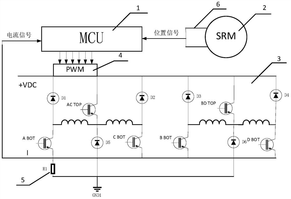
[0036] The specific embodiment of the present invention is as figure 1 As shown, the microcontroller 1 is STM32F030C6, and the power converter 3 adopts an improved four-phase asymmetrical half-bridge structure. The switched reluctance motor 2 is a four-phase 8 / 6-pole switched reluctance motor with a rated speed of 13000r / min. It is powered by the power converter 3, and the current sum of the currents flowing through the four-phase windings is detected by the current sampling resistor 5 and input to The ADC0 port of the microcontroller 1 and the position detection unit 6 are composed of a rotor position measuring gear plate, two slot-type Hall switch devices and corresponding circuits. Microcontroller 1 obtains the state of the two Hall switches by inputting the capture interrupt to determine the current position of the rotor.

[0037]The switched reluctance motor adopts double closed-loop control of speed and current. The actual speed of the motor and the current position of...


PUM


Abstract

The invention discloses a current loop reconstruction method for controlling a four-phase switched reluctance motor, and belongs to the technical field of switched reluctance motor control. The switched reluctance drive system is a rotating speed and current double-closed-loop control system, wherein an outer loop is controlled by a rotating speed loop, an inner loop is controlled by a current loop, and a four-phase switched reluctance motor generally needs four independent current sampling loops so as to increase the cost and the volume of a control circuit, so that in some applications withstrict requirements on volume and cost, four phases are selected to share one sampling loop to detect current, when four phases share one current sampling loop, in order to enable the four-phase switched reluctance motor to accurately feed back each phase of current, a shape function of a current waveform is constructed, current distribution function of each phase is obtained through the shape function of each phase of current, the acquired current is then multiplied by the distribution function of each phase, a four-phase feedback current is reconstructed from a feedback current loop, and theactual accurate current of each phase of the motor is obtained so as to achieve the purpose of accurate and stable operation of the motor.

Description

technical field [0001] The invention belongs to the technical field of switched reluctance motor control, and relates to a current loop reconfiguration method of a switched reluctance motor control system, mainly aiming at reconstructing four current loops based on simulation technology when a four-phase switched reluctance motor has only one current sampling loop, Improve the accuracy of each phase feedback current detection. Background technique [0002] The switched reluctance motor (Switched Reluctance Motor, SRM) has the advantages of simple and firm structure, wide speed range, high efficiency, and good fault tolerance. Especially for four-phase switched reluctance motors, using a suitable power converter main circuit can make the energizing voltage of each phase winding equal to the power supply voltage under the condition of using less power devices. In addition, the low-speed torque ripple of the four-phase switched reluctance motor is small, and the starting is re...

Claims


Application Information

Patent Timeline
Patent Type & Authority Applications(China)
IPC IPC(8): H02P6/06H02P6/17H02P23/00H02P25/08
CPCH02P6/06H02P6/17H02P23/0004H02P25/0805
Inventor 孙建忠杜呼和贺锡之白凤仙
Owner DALIAN UNIV OF TECH
Why Eureka
Try Eureka