Method and arrangement for obtaining and conveying information about occupancy of a vehicle

a technology for obtaining and conveying information and vehicles, applied in vehicle seats, pedestrian/occupant safety arrangements, vehicle seats, etc., can solve the problems of high cost of replacing airbags, child in rear facing child seats, right front passenger seats, etc., to reduce the intensity of light striking, improve sound quality, and reduce the intensity of light reflected

Inactive Publication Date: 2005-09-27
AUTOMOTIVE TECH INT
View PDF72 Cites 102 Cited by
  • Summary
  • Abstract
  • Description
  • Claims
  • Application Information

AI Technical Summary

Benefits of technology

[0030]Briefly, the claimed inventions are methods and arrangements for determining that there is a life form, e.g., a human being, in a vehicle and the location of the life form, i.e., in which seat the life form is situated. This determination is used in various methods and arrangements for, e.g., controlling deployment of occupant restraint devices in the event of a vehicle crash, controlling heating and air-conditioning systems to optimize the comfort for any occupants, controlling an entertainment system as desired by the occupants, controlling a glare prevention device for the occupants, preventing accidents by a driver who is unable to safely drive the vehicle and enabling an effective and optimal response in the event of a crash (either oral directions to be communicated to the occupants or the dispatch of personnel to aid the occupants). Thus, one particular objective of the inventions is to obtain information about occupancy of a vehicle and convey this information to remotely situated assistance personnel to optimize their response to a crash involving the vehicle and / or enable proper assistance to be rendered to the occupants after the crash.
[0054]23. To determine the location of the eyes of a vehicle occupant and the direction of a light source such as the headlights of an oncoming vehicle or the sun and to cause a filter to be placed in such a manner as to reduce the intensity of the light striking the eyes of the occupant.
[0055]24. To determine the location of the eyes of a vehicle occupant and the direction of a light source such as the headlights of a rear approaching vehicle or the sun and to cause a filter to be placed in such a manner as to reduce the intensity of the light reflected from the rear view mirrors and striking the eyes of the occupant.
[0056]25. To determine the location of the ears of one or more vehicle occupants and to use that information to control the entertainment system, e.g., the speakers, so as to improve the quality of the sound reaching the occupants' ears through such methods as noise canceling sound.

Problems solved by technology

Also, a child in a rear facing child seat, which is placed on the right front passenger seat, is in danger of being seriously injured if the passenger airbag deploys.
In addition to eliminating the disturbance of unnecessary airbag deployments, the cost of replacing these airbags will be excessive if they all deploy in an accident.
The danger of deployment induced injuries will exist for side impact airbags as they now do for frontal impact airbags.
Once the system is operational, it would be logical for the system to also incorporate the airbag electronic sensor and diagnostics system (SDM) since it needs to interface with SDM anyway and since they could share computer capabilities which will result in a significant cost saving to the auto manufacturer.
This technology could provide input data to a pattern recognition system but it has limitations related to temperature.
The sensing of the child could pose a problem if the child is covered with blankets.
It also might not be possible to differentiate between a rear facing child seat and a forward facing child seat.
In all cases, the technology will fail to detect the occupant if the ambient temperature reaches body temperature as it does in hot climates.
Its main drawback is cost which is considerably above that of ultrasonic or passive infrared systems.
The wavelength of a particular radar system can limit the ability of the pattern recognition system to detect object features smaller than a certain size.
Once again, however, there is some concern about the health effects of radar on children and other occupants.
The ultrasonic system is the least expensive and potentially provides less information than the optical or radar systems due to the delays resulting from the speed of sound and due to the wave length which is considerably longer than the optical (including infrared) systems.

Method used


Image

  • Method and arrangement for obtaining and conveying information about occupancy of a vehicle
  • Method and arrangement for obtaining and conveying information about occupancy of a vehicle
  • Method and arrangement for obtaining and conveying information about occupancy of a vehicle

Examples


Embodiment Construction

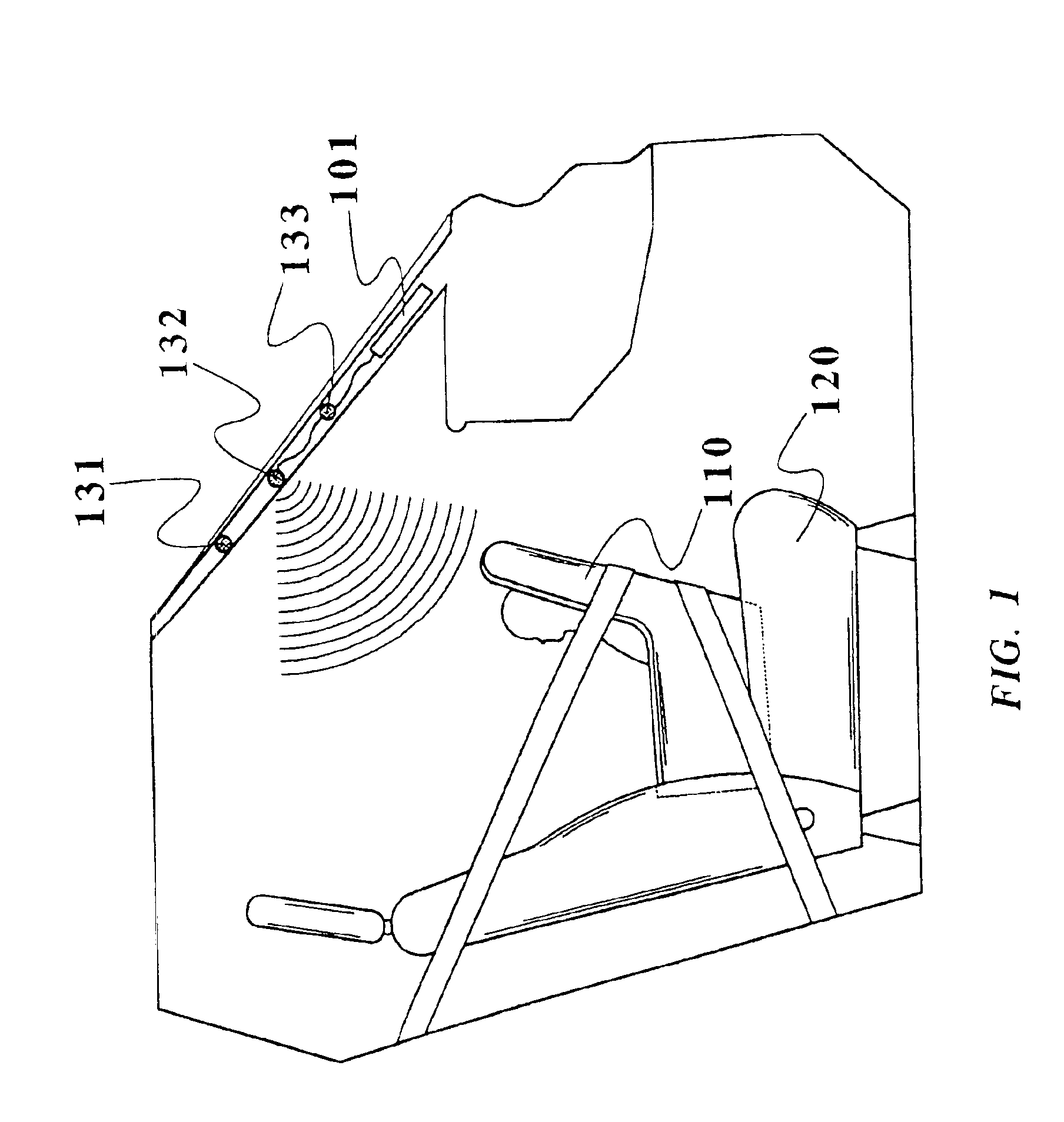
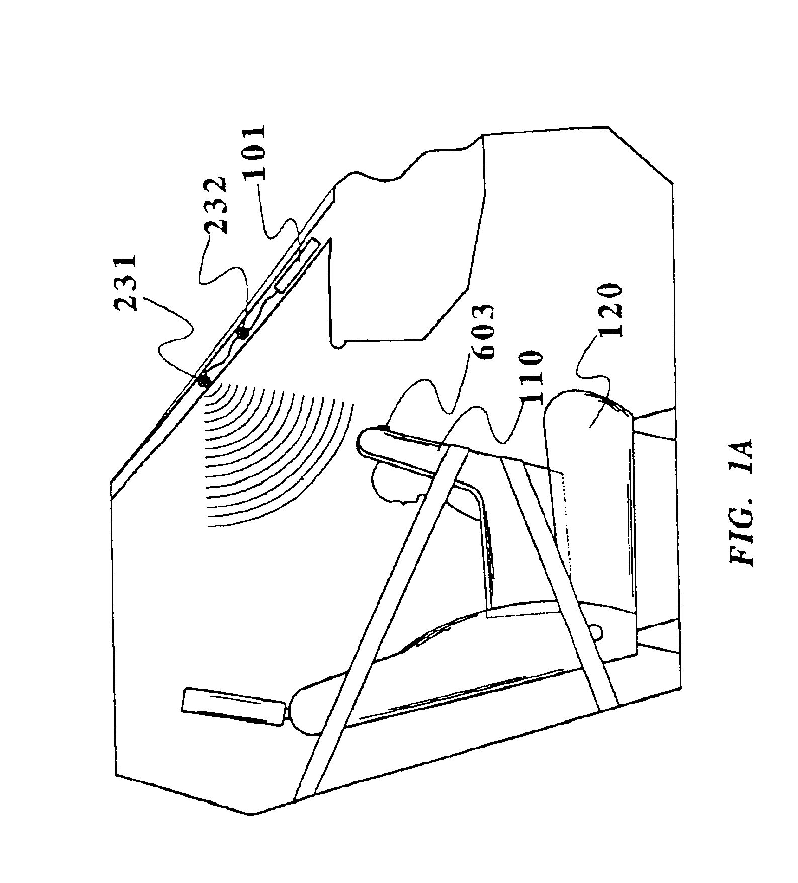
[0116]Referring to the accompanying drawings wherein the same reference numerals refer to the same or similar elements, FIG. 1 is a side view, with parts cutaway and removed of a vehicle showing the passenger compartment containing a rear facing child seat 110 on a front passenger seat 120 and a preferred mounting location for a first embodiment of a vehicle interior monitoring system in accordance with the invention. The interior monitoring system is capable of detecting the presence of an occupant and the rear facing child seat 110. In this embodiment, three transducers 131, 132 and 133 are used, although any number of wave-transmitting transducers or radiation-receiving receivers may be used. Such transducers or receivers may be of the type which emit or receive a continuous signal, a time varying signal or a spacial varying signal such as in a scanning system. One particular type of radiation-receiving receiver for use in the invention is a receiver capable of receiving electrom...


PUM


Abstract

Method and arrangement for obtaining and conveying information about occupancy of a passenger compartment of a vehicle including at least one sensor for obtaining data from the passenger compartment. Information about the occupancy is generated based on the data and transmitted, e.g., through a cellular phone system, to emergency response personnel to enable them to respond accordingly. The information about the occupancy may be generated by a processor applying pattern recognition techniques so that any occupants of the seat may be classified and such classification transmitted to the emergency response personnel. The data may also be used to determine the number of occupants in the vehicle and / or whether the occupants are moving after a crash. The sensors may be a variety of sensors such as an ultrasonic sensor, an electromagnetic wave sensor, an electric field sensor, a chemical sensor, a weight sensor, a motion sensor, a microphone, a heartbeat sensor, a vibration sensor, an acceleration sensor and a capacitance sensor.

Description

CROSS REFERENCE TO RELATED APPLICATIONS[0001]This application is a continuation of U.S. patent application Ser. No. 09 / 838,920 filed Apr. 20, 2001 now U.S. Pat. No. 6,778,672 which in turn is a continuation-in-part of U.S. patent application Ser. No. 09 / 563,556 filed May 3, 2000, now U.S. Pat. No. 6,474,683, which in turn is a continuation-in-part of U.S. patent application Ser. No. 09 / 437,535 filed Nov. 10, 1999, now U.S. Pat. No. 6,712,387, which in turn is a continuation-in-part of U.S. patent application Ser. No. 09 / 047,703 filed Mar. 25, 1998, now U.S. Pat. No. 6,039,139, which in turn is:[0002]1) a continuation-in-part of U.S. patent application Ser. No. 08 / 640,068 filed Apr. 30, 1996, now U.S. Pat. No. 5,829,782, which in turn is a continuation of U.S. patent application Ser. No. 08 / 239,978 filed May 9, 1994, now abandoned, which in turn is a continuation-in-part of U.S. patent application Ser. No. 08 / 040,978 filed Mar. 31, 1993, now abandoned, which in turn is a continuation...

Claims


Application Information

Patent Timeline
Patent Type & Authority Patents(United States)
IPC IPC(8): B60N2/26B60N2/02B60N2/48B60R21/01B60N2/28G06K9/00B60R1/12B60J10/00B60N2/00B60R1/08B60R11/02B60R16/02B60R16/037B60R21/013B60R21/0132B60R21/0134B60R21/015B60R21/16B60R21/20B60R21/215B60R21/231B60R21/26B60R21/276B60R22/20B60R22/48E05F15/00G01F23/00G01F23/20G01F23/296G01S7/41G01S7/48G01S7/539G01S13/04G01S15/04G01S15/06G01S15/87G01S15/88G01S17/88G01S17/89
CPCB60J10/00B60N2/0232B60N2/0248B60N2/0276B60N2/2806B60N2/2863B60N2/4829B60N2/4885B60R1/088B60R11/0241B60R16/037B60R21/0136B60R22/20B60R25/25B60R25/255B60R25/257G01F23/0076G01F23/20G01F23/2962G01S7/417G01S7/4802G01S7/539G01S15/87G01S15/88G01S17/88G06K9/00362B60R21/01554B60R21/01536B60R21/01516B60R21/01534B60R21/01538B60R21/01542B60R21/01552B60R21/0154E05F15/43E05F15/431B60N2/002E05F2015/433B60N2002/0268B60R21/0132B60R21/0134B60R21/21656B60R21/276B60R2001/1223B60R2001/1253B60R2021/0027B60R2021/01315B60R2021/23153B60R2021/26094B60R2021/2765B60R2022/208B60R2022/4825E05Y2900/55G01S13/04G01S15/04G01S15/06G01S17/89G10K2210/1282G10K2210/3219B60N2002/0272B60R21/01548B60R21/01544B60N2/888B60N2/829G01F23/804G06V40/10G06V20/59B60N2/0272B60N2/0268B60N2/02246
Inventor BREED, DAVID S.
Owner AUTOMOTIVE TECH INT
Why Eureka
Try Eureka