
Protective film for a prism lens

a protective film and prism lens technology, applied in the field of transparent synthetic resin films, can solve the problems of scarring and diminishing the commercial value of the prism lens

Inactive Publication Date: 2005-09-27
TSUJIDEN
View PDF9 Cites 23 Cited by
  • Summary
  • Abstract
  • Description
  • Claims
  • Application Information

AI Technical Summary

Benefits of technology

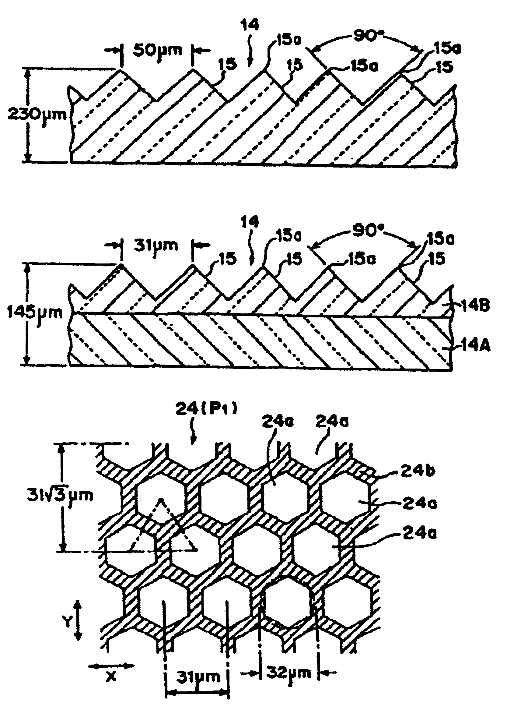
[0016]Although such random dots (protrusions / recesses) on the surface has a complex geometric pattern, it is easy to fabricate a random dot surface such that a multiplicity of flat / convex faces of random spotted protrusion are in substantial contact with a multiplicity of ridges of the prisms at any relative position of the protective film along any two-dimensional orientation on the prism lens.
[0056]Particularly. it is possible to form a three-layered protective film by integrally stacking a second film on the back of the first film and a similar third film having a similar rough surface on the front surface of the first film. Such three-layered film has an extra strength.

Problems solved by technology

However, a problem arises in such LCDs in that the protective film 8 can scratch ridges of the prisms 4a of prism lens 4 and leave scars 5 as shown in FIG. 20 if the protective film 8 is moved relative to the prism lens 4 in the right or left direction as shown in FIG. 21 due to a move during a manufacturing process assembling an LCD panel, or due to thermal expansions / contractions of the protective film 8 during the use of the LCD panel.
These scars will prevent proper distribution of light and diminishes the commercial value of the prism lens 4.

Method used


Image

  • Protective film for a prism lens
  • Protective film for a prism lens
  • Protective film for a prism lens

Examples


second embodiment

[0099]FIG. 7 shows a protective film of the invention, showing a main portion of the film in an enlarged plan view.

[0100]It would be recalled that in the first embodiment described above, the geometrical pattern P1 of the protrusions on the back of the protective film 20 consists of hexagonal protrusions 24a and the recesses 24b surrounding them. In the second embodiment shown here, equilateral hexagonal holes 24c serving as the recesses (shaded area) are formed so that the peripheral regions 24d of the recesses (holes) 24c connect with each other, thereby forming a honey comb pattern P2 of peripheries 24d surrounding the hexagonal recesses (holes) 24c. In other words, the pattern P2 has a net configuration in which equilateral hexagonal recesses 24c are surrounded by contiguous protruding peripheries 24d.

[0101]The recesses (holes) 24c and the protrusions (peripheries) 24d of the pattern P2 have sizes and arrangements that correspond to those of protrusions 24a and the recesses 24b...

third embodiment

[0104]In comparison with the foregoing embodiments where the protective film 20 is provided on the back thereof with a geometric pattern P1 or P2 of hexagonal protrusions 24a or recesses 24c, the third embodiment has a geometric pattern P3 of alternating L-shaped protrusions 24e and rectangular protrusions 24f on the rough surface 24. Protrusions 24e and 24f are surrounded by a contiguous region of recess 24g. In the pattern P3, the recess surrounding the protrusions 24e and 24f extend in the form of a net, as claimed in claim 4.

[0105]Alternatively, the geometric pattern of the rough surface 24 may be formed of alternating L-shaped recesses and rectangular recesses (with the recesses being regions 24e and 24f and the protrusions being the region 24g surrounding the regions 24e and 24f in FIG. 8), as claimed in claim 9.

fourth embodiment

[0106]FIG. 9 illustrates a protective film according to the invention, showing a main portion of the protective film. More particularly, FIG. 9(a) shows the protective film in plan view, and FIG. 9(b) in cross sectional view.

[0107]In the fourth embodiment, the rough surface 24 on the back of the protective film 20 has a non-geometric pattern P4 of randomly distributed or spotted protrusions 24h such that the top ends of the spotted protrusions 24h lie in a single plane 25. The shaded region 24i is a contiguously recessed region surrounding the protrusions 24h. Hence, the pattern P4 is a combination of spotted protrusions 24h surrounded by a net-shaped contiguous recesses 24i, embodying the invention as claimed in claim 2.


PUM


Abstract

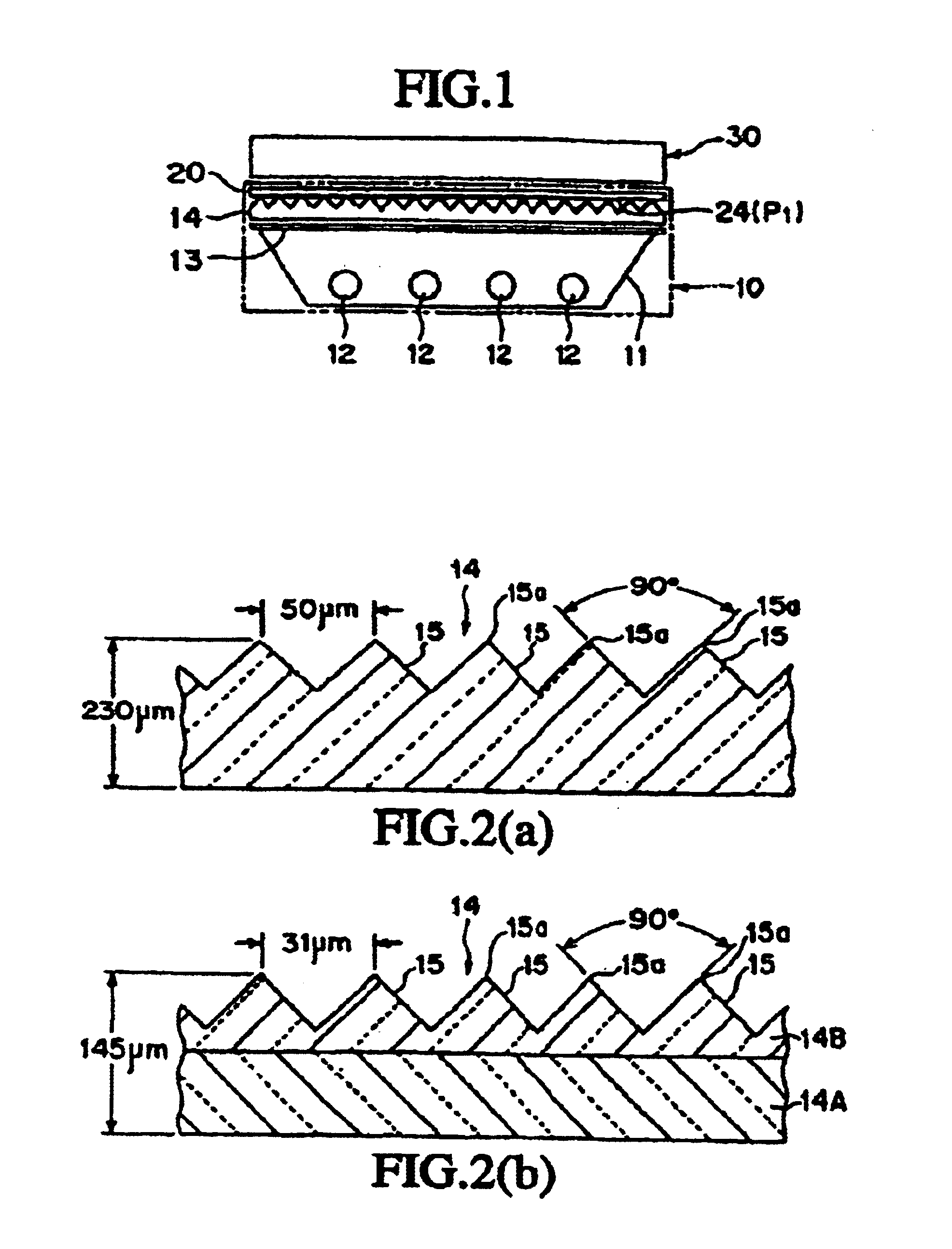
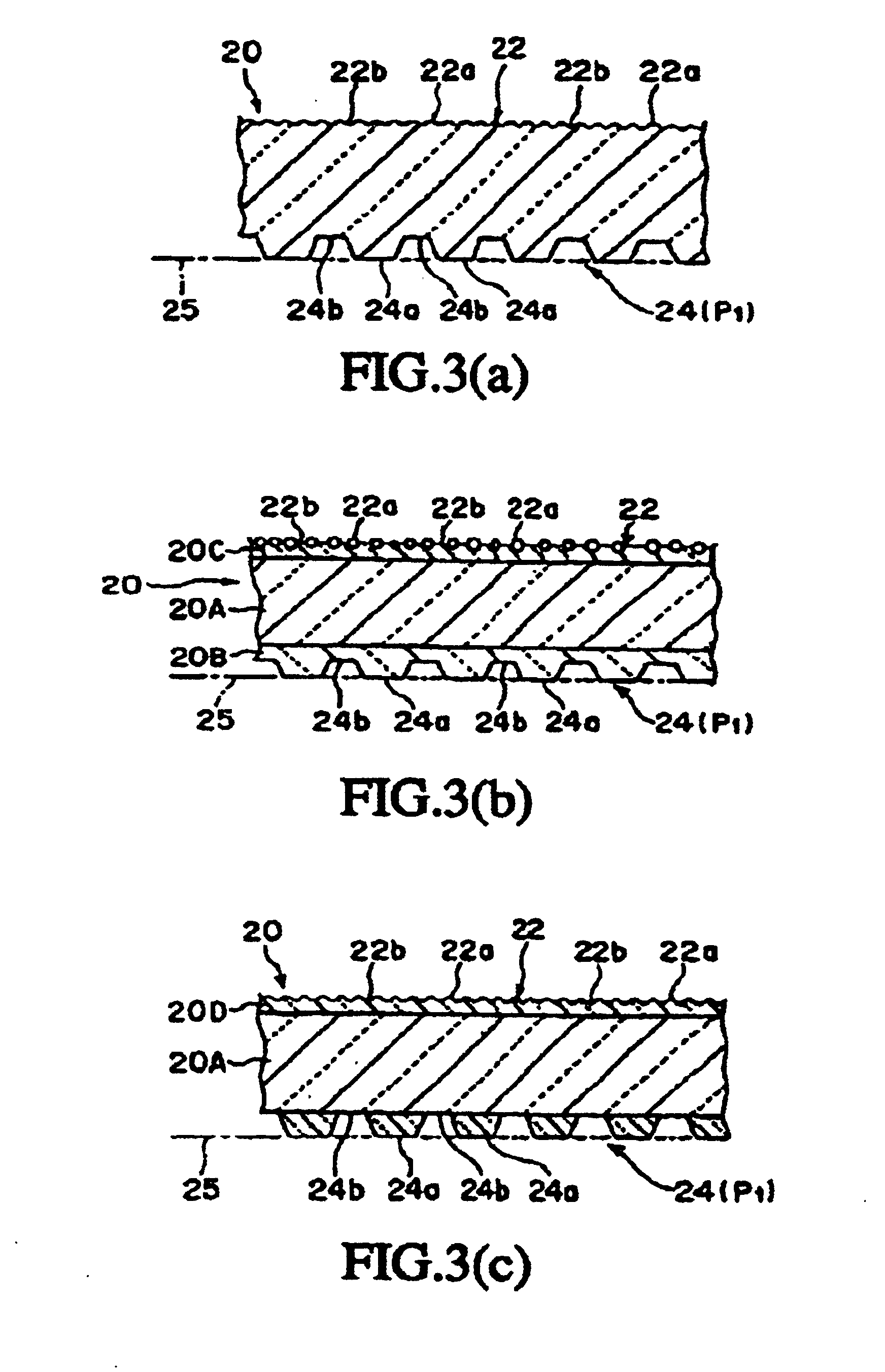
A transparent synthetic resin protective film to be mounted on prisms (15) of a synthetic resin prism lens (14) where a light entering from the side face or the back face emerges from the prism forming face on the front side formed with ridge prisms (15) continuously. A rough surface (24) comprising micro protrusions and recesses for suppressing moire fringes, blur, glare, and inversion is provided at least to the protective film facing the prism (15). The top part of each protrusion (24a) constituting the rough surface (24) is a flat face substantially contained in a single plane (25) and having such a predetermined small extent not recognizable by naked eyes or a convex face of small curvature. The flat faces of the protrusions (24a) is continuous with the edges (15a) of the prisms (15) in any relative position of the protective film (20) and the prism lens (14) in the two-dimensional direction. Since the protrusions (24a) on the protective film (20) side slide smoothly on the prism (15) when the protective film (20) moves relatively to the prism lens (14), the conventional drawback that the edges (15a) of the prism (15) of the prism lens (14) is rubbed and worn by (the protrusions (24a) of) the rough surface (22) on the protective film (20) side is overcome.

Description

[0001]This application is a 371 continuation of PCT Application PCT / JP00 / 05391 filed Aug. 11, 2000, and also claims priority to Japanese application JP 11-237194 filed Aug. 24, 1999; the specifications of which are incorporated by reference herein.FIELD OF THE INVENTION[0002]The invention relates to a transparent synthetic resin film to be mounted on the light emitting faces of prisms of a synthetic resin prism lens and, more particularly, to a protective film for a prism lens having at least on the back thereof a rough surface including micro protrusions / recesses for suppressing Moire fringes, blur, glare, and inversion.BACKGROUND OF THE INVENTION[0003]A liquid crystal display (LCD) typically has a back light section 1 which includes a synthetic resin diffusive plate (diffusive film) 3 and one or two synthetic resin prism lens 4 in front of light sources 2 such as fluorescent light tubes in the order mentioned, and an LCD section 6 including LCD elements in front of the back light ...

Claims


Application Information

Patent Timeline
IPC IPC(8): G02B1/10G02B5/04G02F1/1335G02F1/13
CPCG02B1/105G02B5/045G02F1/133526G02B1/14G02B5/02
Inventor ONISHI, ARATAKA
Owner TSUJIDEN
Learn More