Active receiving array antenna

a technology of receiving array and receiving antenna, which is applied in the field of receiving array antenna, can solve the problems of high interconnection complexity, high power requirement of central local oscillator signal generation, and respect to array antenna production cost, and achieve low noise sensitiveness, low noise factor of receiving channel, and low noise factor

Active Publication Date: 2005-09-27
AIRBUS DEFENCE & SPACE
View PDF12 Cites 9 Cited by
  • Summary
  • Abstract
  • Description
  • Claims
  • Application Information

AI Technical Summary

Benefits of technology

[0016]The filtering properties of the array antenna according to the invention can furthermore be expanded and used in the image frequency range for the suppression of the received power to realize a low noise sensitiveness and low (single sideband) noise factor of the receiving channels. The series connection of the amplifier stage and the mixer can also have a high attenuation of the intermediate frequency, whereby the reception of intermediate frequency signals can be suppressed.
[0017]Another advantage of the receiving array antenna of the invention is that, because of the common distribution network for the local oscillator and calibration signal, there can be a savings of printed circuit board planes when realizing the antenna structure in planar technology. The circuitry in accordance with the invention in the form of a series circuit of low-noise preamplifier and imbalanced mixer can result in a further savings of printed circuit board planes. This provides a further advantage with respect to decreased production costs.

Problems solved by technology

The disadvantage of this interconnection is that the central local oscillator signal must be generated with a very high power when the number of channels is large.
Another disadvantage is that, because of the two separate networks, a high interconnection complexity is necessary.
Further disadvantages with respect to the production costs of the array antenna result from this.
This leads in particular to a partial cancellation of the signals emitted by the antenna when taking the undesirable emission of the local oscillator signal of the array antenna into consideration.

Method used


Image

  • Active receiving array antenna
  • Active receiving array antenna
  • Active receiving array antenna

Examples


Embodiment Construction

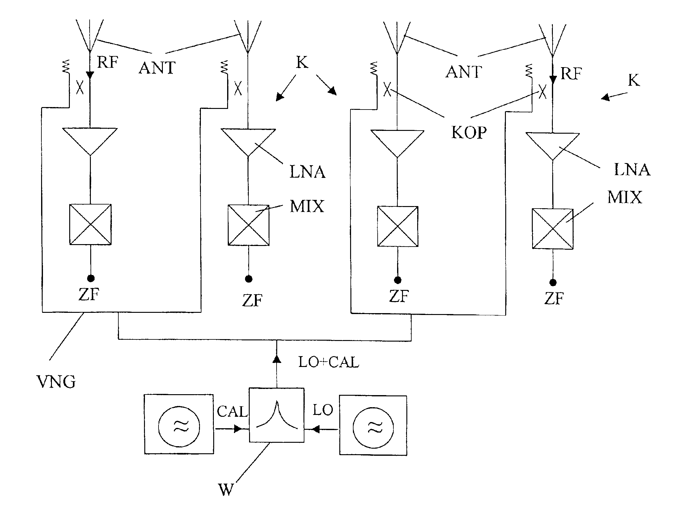
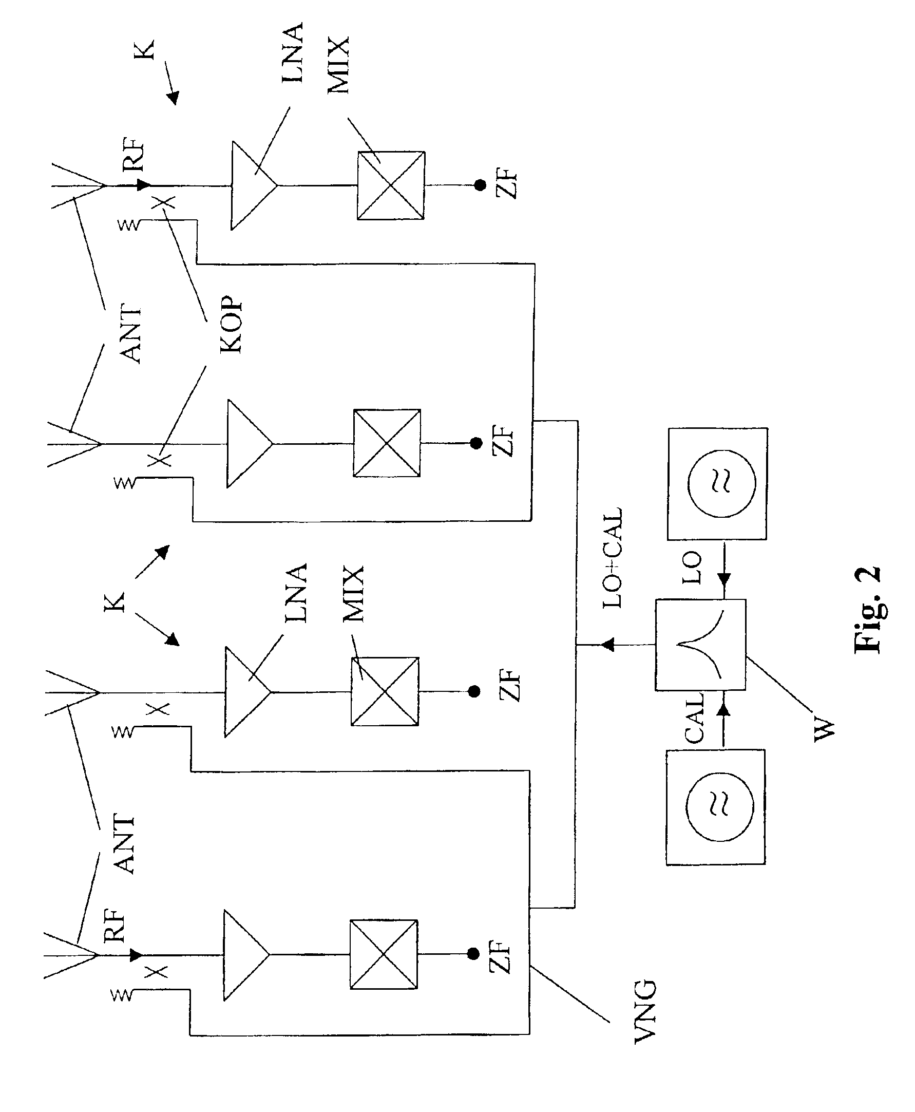
[0029]FIG. 2 shows a receiving array antenna with, for example, 4 channels in an interconnection of the invention with a common distribution network for the local oscillator and calibration signal. Each channel K is configured in this order by a series circuit of an antenna element ANT, a coupler KOP, a low-noise amplifier LNA and a mixer MIX. The amplifier can, of course, consist of several amplifier stages.

[0030]The intermediate frequency signal ZF of the corresponding channel is tapped at the output of the mixer MIX. The individual couplers KOP of the channels K are connected to each other via a common distribution network VNG. In this distribution network VNG, a centrally generated calibration signal CAL and a local oscillator signal LO are supplied by means of a T-switch W.

[0031]A first advantageous embodiment for coupling the distribution network for the local oscillator and calibration signal to the circuit is shown in FIG. 3. The distribution network VNG is coupled By means ...


PUM


Abstract

A receiving array antenna with a variety of channels for converting received signals from receiving antenna elements (ANT) into an intermediate frequency signal (ZF) by using a circuit having one or several preamplifiers (LNA) and a mixer (MIX) connected in series, whereby a centrally generated local oscillator signal (LO) and calibration signal (CAL) are supplied to the circuit. A common distribution network (VNG) is available for the central oscillator signal (LO) and calibration signal (CAL), which is interconnected in such a way that the central local oscillator signal (LO) and calibration signal (CAL) is coupled into the circuit at the output of the receiving antenna element (ANT).

Description

BACKGROUND AND SUMMARY OF THE INVENTION[0001]This application claims the priority of Germany Application No. 101 57 216.6-35, filed Nov. 22, 2001, the disclosure of which is expressly incorporated by reference herein.[0002]The invention concerns a receiving array antenna for converting received signals from antenna elements into an intermediate frequency signal.[0003]In active receiving array antennas, which usually consist of individual elements or subgroup elements, the received signals (radio frequency (RF) or high frequency signals (HF)) are converted to an intermediate frequency range (baseband). Digital or analog signal overlay, so-called “beam forming,” generate electronically controlled antenna characteristics in the intermediate frequency or baseband range. For this purpose, a conversion of the signals of the antenna elements or the subgroup elements takes place in a circuit including low-noise preamplifiers and frequency converters (mixer circuits). A local oscillator sign...

Claims


Application Information

Patent Timeline
Patent Type & Authority Patents(United States)
IPC IPC(8): H01Q3/26H04B7/08H04B17/00
CPCH01Q3/26H04B7/0848H01Q3/267H04B17/20
Inventor SOLBACH, KLAUS
Owner AIRBUS DEFENCE & SPACE
Why Eureka
Try Eureka