
Apparatus and method for automated protein design

a protein design and protein technology, applied in the field of automatic protein design, can solve the problems of hampered development of improved, second generation, proteins, and many designed proteins lacking the structural specificity of native proteins

Inactive Publication Date: 2005-09-27
CALIFORNIA INST OF TECH
View PDF10 Cites 134 Cited by
  • Summary
  • Abstract
  • Description
  • Claims
  • Application Information

AI Technical Summary

Benefits of technology

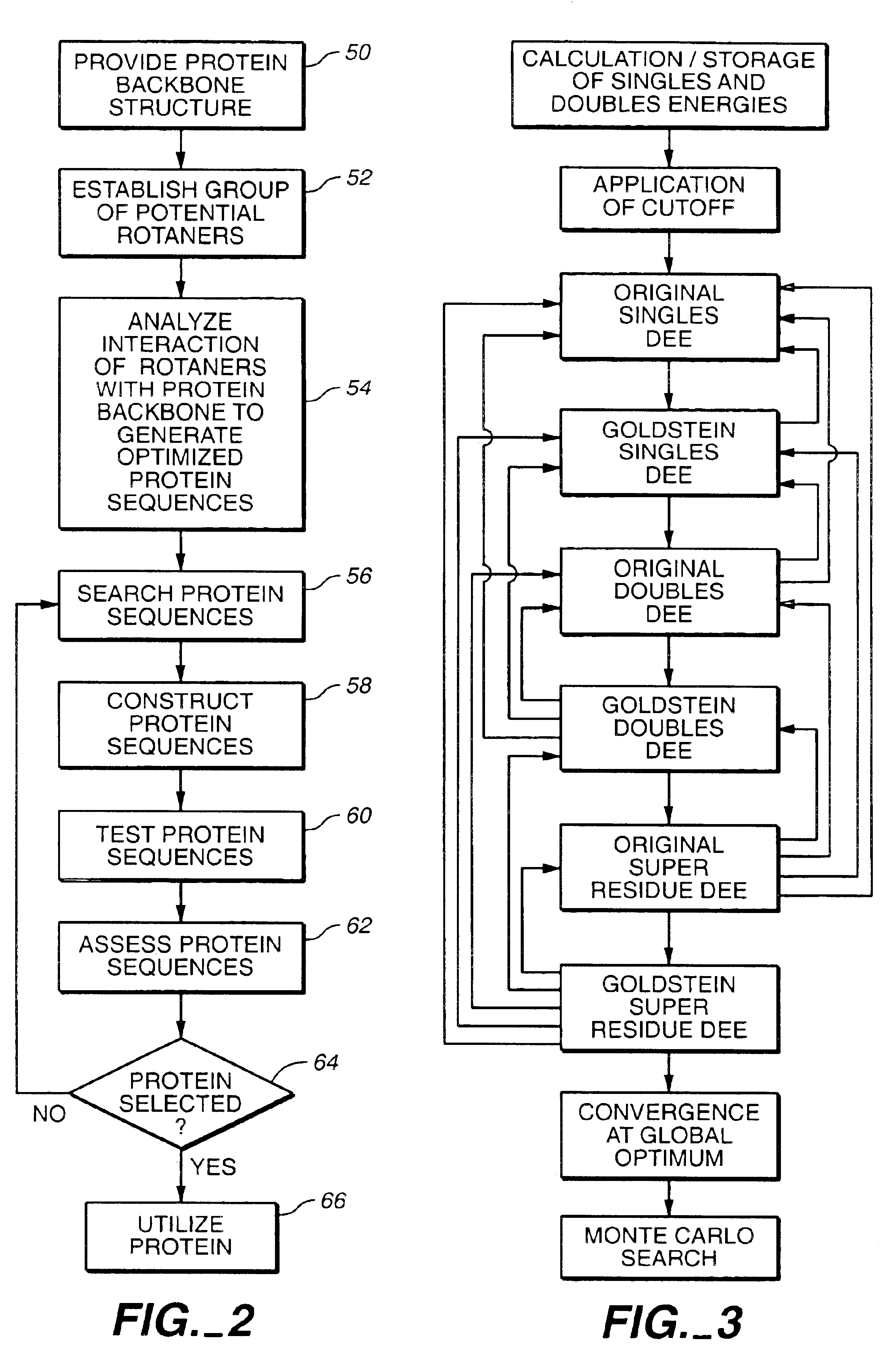
[0009]In accordance with the objects outlined above, the present invention provides methods executed by a computer under the control of a program, the computer including a memory for storing the program. The method comprising the steps of receiving a protein backbone structure with variable residue positions, establishing a group of potential rotamers for each of the variable residue positions, wherein at least one variable residue position has rotamers from at least two different amino acid side chains, and analyzing the interaction of each of the rotamers with all or part of the remainder of the protein backbone structure to generate a set of optimized protein sequences. The methods further comprise classifying each variable residue position as either a core, surface or boundary residue. The analyzing step may include a Dead-End Elimination (DEE) computation. Generally, the analyzing step includes the use of at least one scoring function selected from the group consisting of a Van der Waals potential scoring function, a hydrogen bond potential scoring function, an atomic solvation scoring function, a secondary structure propensity scoring function and an electrostatic scoring function. The methods further comprise altering the protein backbone prior to the analysis, comprising altering at least one supersecondary structure parameter value. The methods may further comprise generating a rank ordered list of additional optimal sequences from the globally optimal protein sequence. Some or all of the protein sequences from the ordered list may be tested to produce potential energy test results.

Problems solved by technology

Though the correct secondary structure and overall tertiary organization seem to have been attained by several of the above techniques, many designed proteins appear to lack the structural specificity of native proteins.
In addition, the qualitative nature of many design approaches has hampered the development of improved, second generation, proteins because there are no objective methods for learning from past design successes and failures.

Method used


Image

  • Apparatus and method for automated protein design
  • Apparatus and method for automated protein design
  • Apparatus and method for automated protein design

Examples


example 1

Protein Design Using van der Waals and Atomic Solvation Scoring Functions with DEE

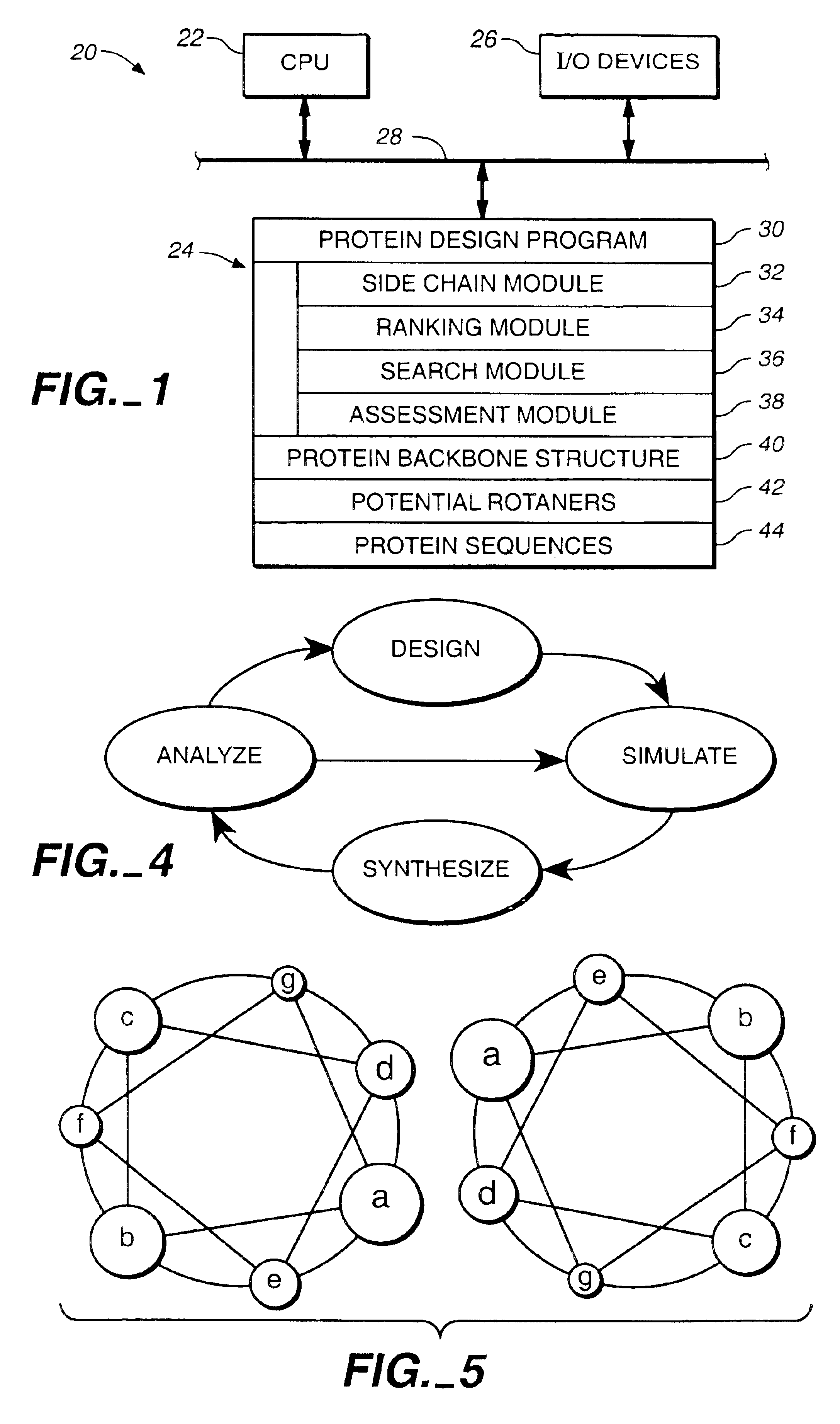
[0175]A cyclical design strategy was developed that couples theory, computation and experimental testing in order to address the problems of specificity and learning (FIG. 4). Our protein design automation (PDA) cycle is comprised of four components: a design paradigm, a simulation module, experimental testing and data analysis. The design paradigm is based on the concept of inverse folding (Pabo, Nature 301:200 (1983); Bowie, et al., Science 253:164-170 (1991)) and consists of the use of a fixed backbone onto which a sequence of side-chain rotamers can be placed, where rotamers are the allowed conformations of amino acid side chains (Ponder, etal., (1987) (supra)). Specific tertiary interactions based on the three dimensional juxtaposition of atoms are used to determine the sequences that will potentially best adopt the target fold. Given a backbone geometry and the possible rotamers allowed for each ...

example 2

Automated Design of the Surface Positions of Protein Helices

[0207]GCN4-p1, a homodimeric coiled coil, was again selected as the model system because it can be readily synthesized by solid phase techniques and its helical secondary structure and dimeric tertiary organization ease characterization. The sequences of homodimeric coiled coils display a seven residue periodic hydrophobic and polar pattern called a heptad repeat, (a•b•c•d•e•f•g) (Cohen & Parry, supra). The a and d positions are buried at the dimer interface and are usually hydrophobic, whereas the b, c, e, f, and g positions are solvent exposed and usually polar (FIG. 5). Examination of the crystal structure of GCN4-p1 (O'Shea, et al., supra) shows that the b, c, and f side chains extend into solvent and expose at least 55% of their surface area. In contrast, the e and g residues bury from 50 to 90% of their surface area by packing against the a and d residues of the opposing helix. We selected the 12 b, c, and f residue p...

example 3

Design of a Protein Containing Core, Surface and Boundary Residues Using van der Waals, H-Bonding, Secondary Structure and Solvation Scoring Functions

[0224]In this example, core, boundary and surface residue work was combined. In selecting a motif to test the integration of our design methodologies, we sought a protein fold that would be small enough to be both computationally and experimentally tractable, yet large enough to form an independently folded structure in the absence of disulfide bonds or metal binding sites. We chose the ββα motif typified by the zinc finger DNA binding module (Pavletich, et al. (1991) (supra)). Though it consists of less than 30 residues, this motif contains sheet, helix, and turn structures. Further, recent work by Imperiali and coworkers who designed a 23 residue peptide, containing an unusual amino acid (D-proline) and a non-natural amino acid (3-(1,10-phenanthrol-2-yl)-L-alanine), that takes this structure has demonstrated the ability of this fold ...


PUM

PropertyMeasurementUnit
angle degreeaaaaaaaaaa

Abstract

The present invention relates to apparatus and methods for quantitative protein design and optimization.

Description

[0001]This application claims the benefit of U.S. Ser. Nos. 60 / 043,464, filed Apr. 11, 1997, 60 / 054,678, filed Aug. 4, 1997, 60 / 061,097, filed Oct. 3, 1997, 60 / 087,561, filed Jun. 1, 1998, and is a continuing application of U.S. Ser. No. 09 / 058,459, filed Apr. 10, 1998, now U.S. Pat. No. 6,188,965 and U.S. Ser. No. 09 / 127,926, filed Jul. 31, 1998, now U.S. Pat. No. 6,269,312.FIELD OF THE INVENTION[0002]The present invention relates to an apparatus and method for quantitative protein design and optimization.BACKGROUND OF THE INVENTION[0003]De novo protein design has received considerable attention recently, and significant advances have been made toward the goal of producing stable, well-folded proteins with novel sequences. Efforts to design proteins rely on knowledge of the physical properties that determine protein structure, such as the patterns of hydrophobic and hydrophilic residues in the sequence, salt bridges and hydrogen bonds, and secondary structural preferences of amino ...

Claims


Application Information

Patent Timeline
Patent Type & Authority Patents(United States)
IPC IPC(8): C07K1/00C07K14/00C12N15/10G06F17/50C12N15/09C12N1/00C12N1/15C12N1/19C12N1/21C12N5/10G16B15/20G16B20/00G16B20/50G16B30/00
CPCC07K1/00C07K1/003C07K14/001C12N15/1034C12N15/1089G06F19/16G06F19/18G06F19/22G16B15/00G16B20/00G16B30/00G16B15/20G16B20/50
Inventor MAYO, STEPHEN L.DAHIYAT, BASSIL I.GORDON, D. BENJAMINSTREET, ARTHURSU, YAOYING
Owner CALIFORNIA INST OF TECH
Learn More