Image pick-up apparatus and image pick-up system

a technology of image pick-up and image, which is applied in the direction of optical radiation measurement, radiation control devices, instruments, etc., can solve the problems of random noise component, large effect on image quality degradation, and inability to detect the noise of the sour

Inactive Publication Date: 2005-10-04
CANON KK
View PDF3 Cites 117 Cited by
  • Summary
  • Abstract
  • Description
  • Claims
  • Application Information

AI Technical Summary

Benefits of technology

[0020]In order to solve the above problem, the present invention provides an image pick-up apparatus comprising an area sensor driven by matrix driving, and a reference supply circuit for supplying a reference voltage for driving of the area sensor, wherein the reference voltage is supplied through a low-pass filter (LPF) coupled to the reference supply circuit.
[0021]A cutoff frequency of the low-pass filter is determined so that an effective value of noise of the reference voltage having passed through the low-pass filter becomes not more than one tenth of an effective value of random noise produced in pixels of the area sensor.

Problems solved by technology

However, the supply circuit such as series regulator IC or the like has a random noise component due to flicker noise and thermal noise of semiconductors.
Such line noise appeared in a stripe pattern in an image reproduced from the signal read by the area sensor, and degraded the quality of the image in some cases.
Particularly, high frequency components out of noise components of the reference voltages become beatlike line noise through sampling with the SMPL signal and are considered to have great effect on degradation of image quality.
The occurrence of these line noise sometimes posed a problem in particular in the case where it was necessary to acquire the image data with a high degree of accuracy, e.g., in the case of X-ray image pick-up apparatus and the like.

Method used


Image

  • Image pick-up apparatus and image pick-up system
  • Image pick-up apparatus and image pick-up system
  • Image pick-up apparatus and image pick-up system

Examples


embodiment 1

(Embodiment 1)

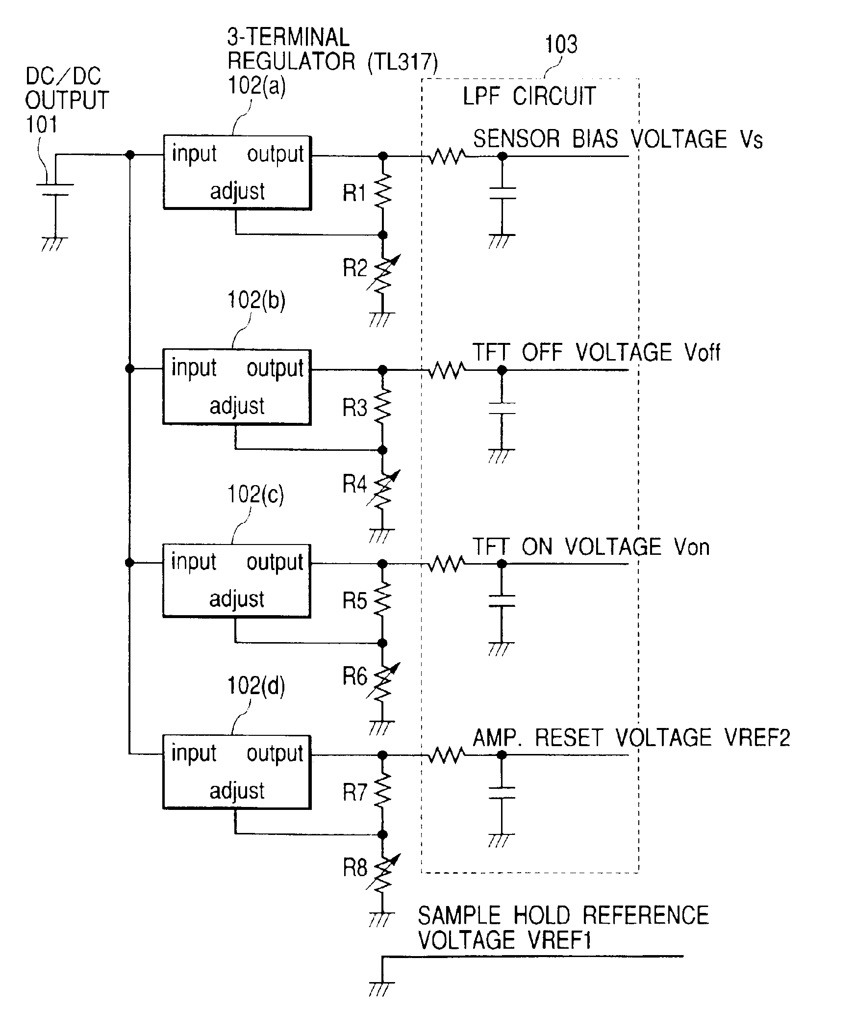
[0034]FIG. 1 is a schematic equivalent circuit diagram of the reference supply circuit in the present embodiment. The drive timing and others in the present embodiment can be similar to those in the conventional example.

[0035]In the present embodiment, low-pass filter (LPF) circuits are added to outputs of regulator IC. The DC output 101 from the DC / DC converter (for example, DC / DC converter of the FIG. 9), the DC power, etc. is outputted by IC102(a)-102(d). The random noise of the regulator IC appears in the form of line noise in an image and can degrade the image quality. Particularly, high-frequency noise components provide great negative effect on the image quality. This is because the effective value of thermal noise of the regulators is determined by the product of noise density N (V / √{square root over (Hz)}) and the bandwidth B(√{square root over (Hz)}).

[0036]Namely, an effective means for reducing the effective value of noise of the regulators to decrease the l...

embodiment 2

(Embodiment 2)

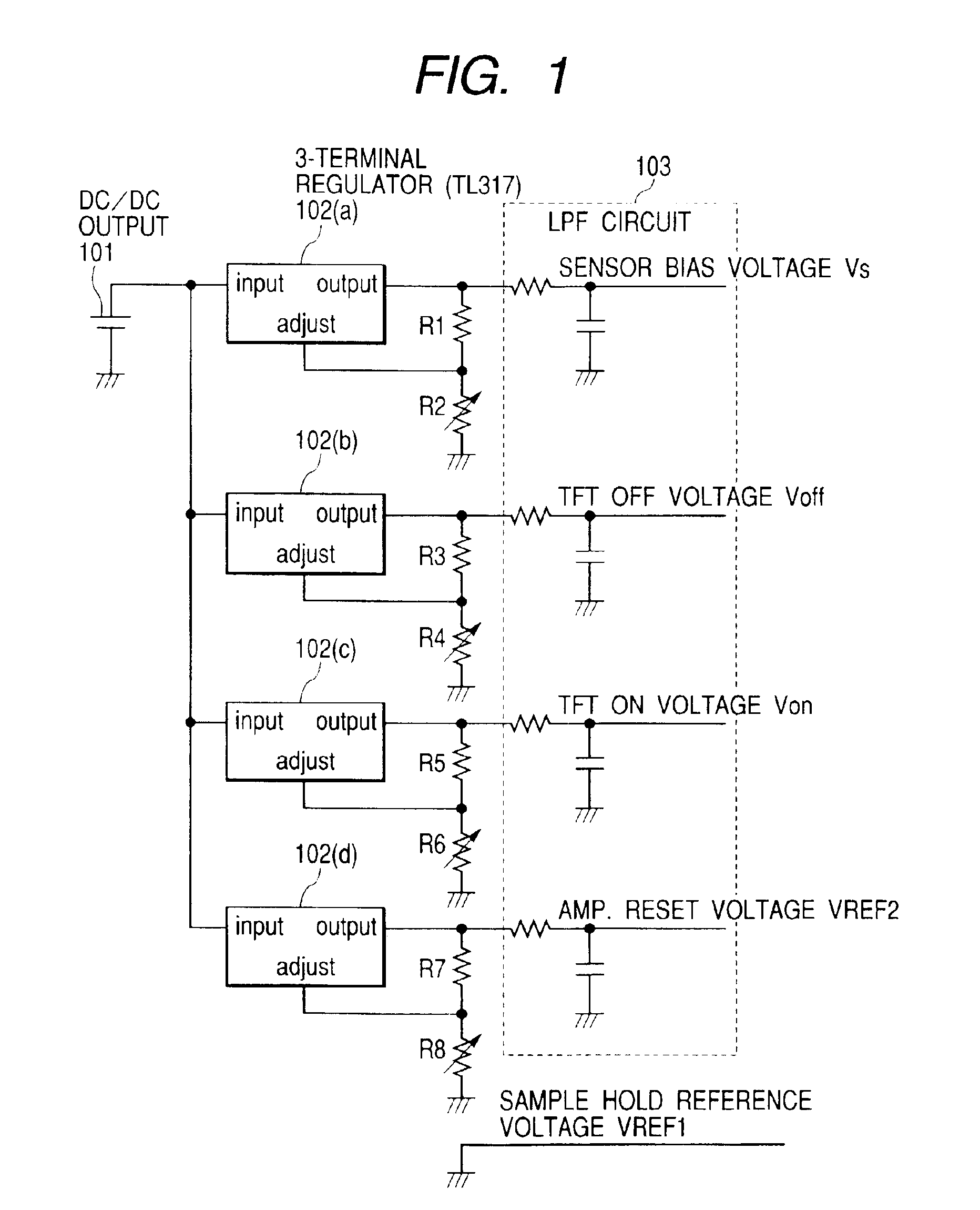
[0047]FIG. 2 is a schematic circuit diagram of the reference supply circuit in the present embodiment. The equivalent circuit diagram, the drive timing, etc. in the present embodiment are similar to those in the conventional example.

[0048]A point to be noted in the present embodiment is that amplifiers are further coupled to the outputs of the LPFs in Embodiment 1. This method is effective in the case where the reference voltages need to be supplied in low impedance.

[0049]It is, however, necessary to pay attention to selection of the amplifiers coupled to the outputs of the LPFs when the configuration of the present embodiment is employed. In order to reduce the line noise, it is desirable to select the amplifiers with the noise density of not more than 3.3 nV / √{square root over (Hz)}. (It is particularly desirable to select them in the frequency region of 100 Hz to 100 kHz.) Describing this in further detail, the random noise of the area sensor used in the X-ray image...

embodiment 3

[0050]FIG. 3 shows an application example of the above embodiments to the image pick-up system. The present embodiment is an X-ray image pick-up system for taking an X-ray image, and the above embodiments are applied to X-ray image pick-up apparatus 6040. An X-ray tube 6050 as an X-ray generator generates X-rays 6060, the X-rays 6060 travel through an observing portion 6062 such as the chest part or the like of a patient or subject 6061, and they are then incident to the X-ray image pick-up apparatus 6040. The incident X-rays carry information about the interior of the subject 6061. The X-ray image pick-up apparatus 6040 acquires electrical information in correspondence to the incidence of X-rays. This information is converted into digital data, the digital data is subjected to image processing in an image processor 6070 as an image processing means, and the resultant image can be observed on a display 6080 as a display means placed in a control room.

[0051]This information can also ...


PUM


Abstract

An image pick-up apparatus and an image pick-up system constructed to prevent occurrence of random noise in a photographed image due to a random noise component produced in a reference supply circuit. An image pick-up apparatus has an area sensor driven by matrix driving, and a reference supply circuit for supplying a reference voltage for driving of the area sensor, and the reference voltage is supplied through a low-pass filter (LPF) coupled to the reference supply circuit. Further, a cutoff frequency of the low-pass filter preferably is determined so that an effective value of noise of the reference voltage having passed through the low-pass filter becomes not more than one-tenth of an effective value of random noise produced in pixels of the area sensor.

Description

BACKGROUND OF THE INVENTION[0001]1. Field of the Invention[0002]The present invention relates to image pick-up apparatus such as radiographic apparatus and the like and, more particularly, to image pick-up apparatus and an image pick-up system provided with a reference supply circuit for supplying a reference voltage for driving of an area sensor.[0003]2. Related Background Art[0004]A conventional example of image pick-up apparatus will be described below with the drawings. FIG. 7 is an equivalent circuit diagram of the conventional example and FIGS. 8A and 8B are diagrams showing its drive timing and output. As shown in FIG. 7, the conventional apparatus is provided with an area sensor in which pixels p1.1-3.3, each consisting of a photodiode as a detecting element and a TFT as a switching device for the photodiode, are arranged in a two-dimensional array and which is driven by matrix driving; a gate drive device 2 for driving the TFTs of the area sensor; a read device 1 to which s...

Claims


Application Information

Patent Timeline
Patent Type & Authority Patents(United States)
IPC IPC(8): G01J1/00G01T1/24G01T1/00H01L31/101G01T1/175G01T1/20H01L27/14H01L27/146H04N5/32H04N5/335H04N5/357H04N5/374
CPCG01T1/2018G01T1/24H04N5/32H04N5/3577H04N5/3658H04N5/374H04N5/3765H04N5/378H01L27/14609H01L27/14676H04N25/617H04N25/677H04N25/745H04N25/76H04N25/75G01T1/20184
Inventor KAMESHIMA, TOSHIO
Owner CANON KK
Why Eureka
Try Eureka