Millimeter-wave signal transmission device

a transmission device and millimeter-wave technology, applied in the direction of waveguides, electrical devices, multiple-port networks, etc., can solve the problems of difficulty in transmitting mm-wave signals, limited distance over which signals may be communicatively connected to parallel transmission lines, etc., and achieve the effect of large distances between circuits and efficiency

Inactive Publication Date: 2005-10-04
AUTOLIV ASP INC
View PDF17 Cites 153 Cited by
  • Summary
  • Abstract
  • Description
  • Claims
  • Application Information

AI Technical Summary

Benefits of technology

[0006]The present invention provides a mm-wave signal transition which overcomes the problems of the prior art. Specifically, the transition of the present invention uses a transducer to convert signals between transverse electromagnetic (TEM) and waveguide modes, rather than relying on the precise positioning of a transmission line relative to a waveguide to launch a signal down the waveguide. By using a transducer, the sensitive signal conversion between TEM mode and waveguide mode is performed in a single, modular unit, which lends itself to mass manufacturing using well-known techniques. Once the delicate operation of converting a signal between TEM and waveguide modes is performed, the converted signal can be transmitted to an orthogonally positioned transmission line or waveguide with relative ease. If desired, the signal can then be converted back to either a TEM mode or waveguide mode signal for transmission down a different orthogonally positioned transmission line or waveguide. This allows the signal to be transmitted over various types of transmission lines over relatively large distances between circuits with efficiency.
[0007]This approach offers a number of advantages over prior art approaches with respect to both manufacturing and performance. As mentioned above, since the TEM / waveguide mode conversion is performed in a transducer, which can be manufactured discretely using well-known techniques, the need for close tolerance positioning between the other components of the transition is alleviated, thereby facilitating large-scale manufacturing techniques and modularization. For example, the waveguide need not be precisely aligned with the transition line, but may instead be based on a relatively loosely toleranced borehole through a support plate. This borehole may be adapted to receive a separately manufactured, modular waveguide filler to aid in the propagation of the waveguide mode signal. Additionally, by converting the TEM / waveguide mode in a modular transducer, there is no need to interconnect probes or the like through soldering or other welding techniques which are time-consuming and prone to failure or performance variations. The transducer not only simplifies the assembly of the transition, but also, in its preferred embodiment, it is planar and eliminates the need for back short, thereby simplifying its own manufacture. Therefore, the present invention's exploitation of a transducer in a transition offers significant manufacturing benefits over the prior art.
[0008]In addition to the manufacturing benefits of the present invention, it also offers important performance advantages over the prior art. Specifically, by converting between TEM and waveguide modes in a relatively simple, modular unit, a complex assembly of components is eliminated along with its attendant inefficiencies and variances. This results in a transition that provides consistent performance with both low insert loss and low reflective loss. Additionally, since the signal transition between orthogonal transmission lines is performed by converting the mode of the signal, the distance over which signals may be communicatively connected to parallel transmission lines is limited by the loss of the vertical hollow-waveguide which can be relatively low. This is in stark contrast to many prior art devices which experience difficulty in transmitting mm-wave signals between parallel transmissions that are further than 10% of the operating signal's wavelength. Finally, since the transition does not use probes or similar antennas like devices to launch the signal into the waveguide, radiation losses are very low and there is no need for a back short.

Problems solved by technology

Additionally, since the signal transition between orthogonal transmission lines is performed by converting the mode of the signal, the distance over which signals may be communicatively connected to parallel transmission lines is limited by the loss of the vertical hollow-waveguide which can be relatively low.
This is in stark contrast to many prior art devices which experience difficulty in transmitting mm-wave signals between parallel transmissions that are further than 10% of the operating signal's wavelength.

Method used


Image

  • Millimeter-wave signal transmission device
  • Millimeter-wave signal transmission device
  • Millimeter-wave signal transmission device

Examples


Embodiment Construction

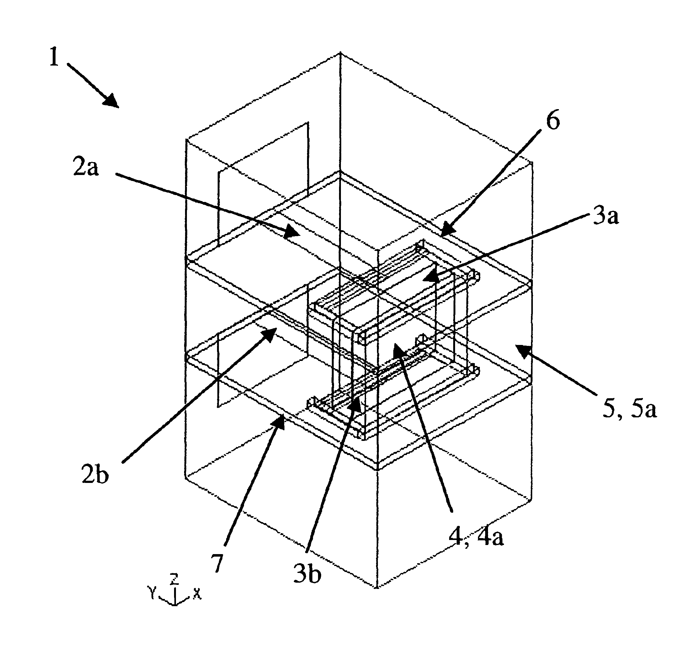
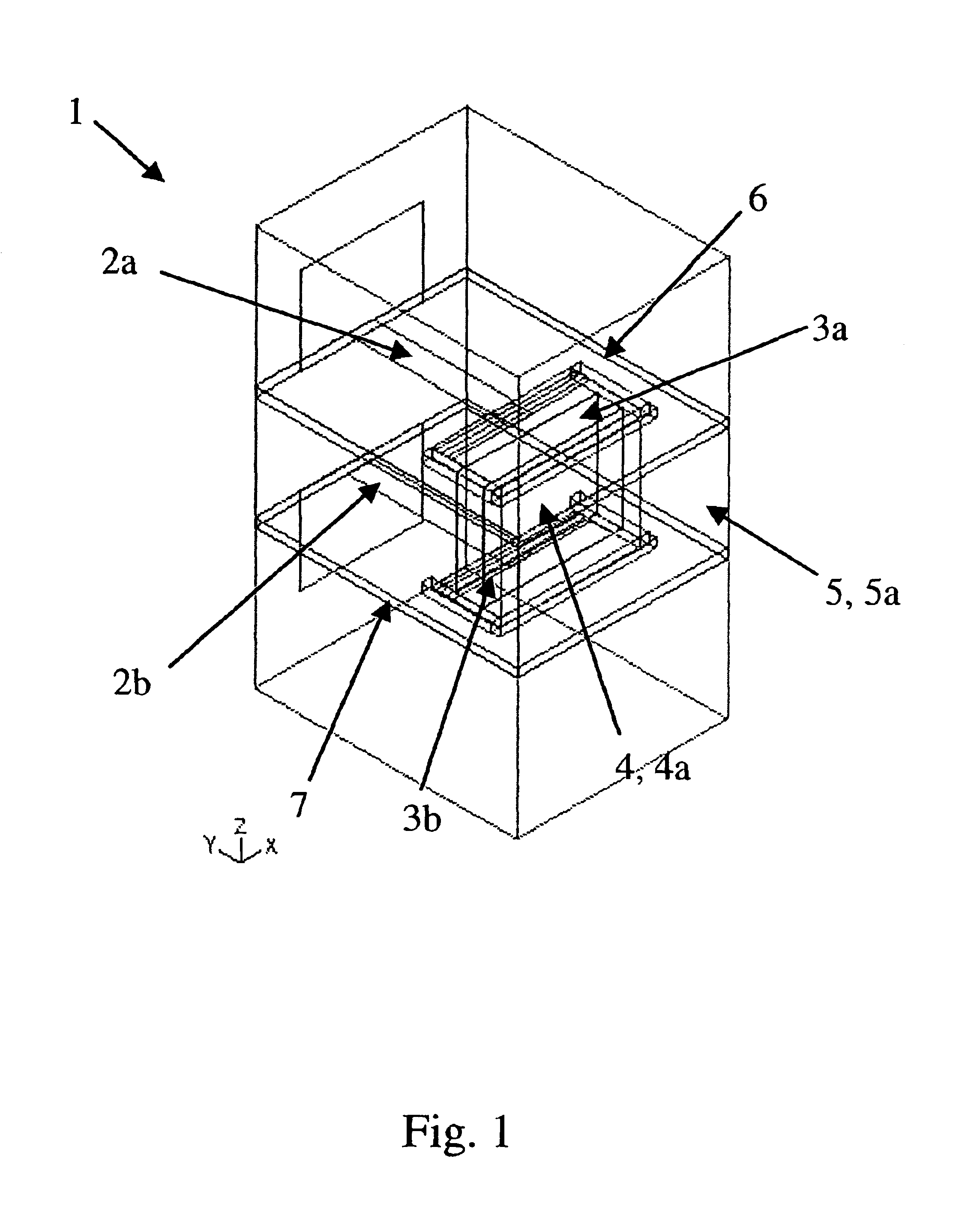
[0017]Referring to FIG. 1, a preferred embodiment of the signal transition 1 of the present invention is shown. As used herein, the term “transition” refers to any device either integral, integrally-molded or an assembly of discrete components which is used to transmit a mm-wave signal from one transverse plane to another one. As used herein, the term “mm-wave signal” refers to a high-frequency electrical signal which may be propagating in a number of different forms, including, for example, in a transverse electromagnetic (TEM) mode or in a waveguide mode. As used herein, the term “TEM mode” refers collectively to both a true TEM pattern and a quasi-TEM pattern. The concepts of TEM, quasi-TEM, and hollow waveguide fields are well known and will not be addressed specifically herein. Suffice it to say though, that in a true TEM mode the electrical field, the magnetic field and the direction of wave travel are all orthogonal to each other, while in a quasi-TEM mode, the electrical fie...


PUM


Abstract

A transition for transmitting a mm-wave signal from one plane to another, the transition comprising: (a) first and second transmission lines on parallel planes; (b) a third transmission line orthogonal to the first and second transmission lines, wherein either the first and second transmission lines are suitable for transmitting a TEM mode signal and the third transmission line is suitable for transmitting a waveguide mode signal, or the third transmission line is suitable for transmitting a TEM mode signal and the first and second transmission lines are suitable for transmitting a waveguide mode signal; and (c) first and second transducers, the first transducer coupled between the first and third transmission lines, the second transducer coupled between the second and third transmission lines, each of the transducers suitable for converting a TEM mode signal to a waveguide mode signal.

Description

FIELD OF INVENTION[0001]This invention relates generally to a millimeter-wave signal transition, and, more specifically, to a signal transition for transiting a mm-wave signal between two different geometric planes.BACKGROUND OF INVENTION[0002]Automated cruise control (ACC) for automobiles is gaining popularity in recent years. ACC allows a user to set the desired speed and minimum following distance of his / her vehicle. The system then controls the speed of the user's vehicle to ensure that the minimum following distance is maintained. Critical to such systems is the effective implementation of a radar system, typically those operating in the 77 GHz range. Such systems must be capable of transmitting, receiving and manipulating millimeter-wave (mm-wave) signals. As with most electronics, there is continuous pressure to miniaturize such systems to reduce their space and material requirements. Consequently, the circuitry of these systems is becoming more compact and sophisticated, emp...

Claims


Application Information

Patent Timeline
Patent Type & Authority Patents(United States)
IPC IPC(8): H01P5/107H01P5/10H01P1/02
CPCH01P5/107
Inventor KINAYMAN, NOYANDOUGLAS, ALLAN S.CUSHMAN, JOHN F.
Owner AUTOLIV ASP INC
Why Eureka
Try Eureka