Enhanced metric for bit detection on fading channels with unknown statistics

a bit detection and statistics technology, applied in the field of communication, can solve the problems of difficult to infer the phase of the received signal from the modulated data symbols, the demodulation of phase or frequency modulated signals, and the distortion of the transmitted signal, etc., and achieve the effect of improving performan

Inactive Publication Date: 2005-10-04
LUCENT TECH INC
View PDF8 Cites 46 Cited by
  • Summary
  • Abstract
  • Description
  • Claims
  • Application Information

AI Technical Summary

Benefits of technology

[0007]In an embodiment of the invention, a UMTS receiver uses PSAM in demodulating a received BPSK signal. The UMTS receiver uses a single column look-up table (excluding index) to provide a scale factor for use in demodulation of the received signal. In particular, a ratio of the transmitted energy per pilot symbol to the transmitted energy per data symbol provides an index into the look-up table to return a value for the scale factor, which provides better performance during periods when the fading distribution is unknown.

Problems solved by technology

However, in a typical wireless channel, such a transmitted signal undergoes distortion due to fading and path loss in addition to additive noise and interference.
This poses a problem in the demodulation of phase or frequency modulated signals.
The fading channel causes rapid changes in the phase thus making it very difficult to infer the phase of the received signal from the modulated data symbols.
While each scheme provides a mechanism for either not requiring knowledge of the exact phase at the receiver or inferring it more accurately, there is an associated loss in performance.
For example, non-coherent and differential modulation result in an increase in the required signal-to-noise ratio (SNR) compared to coherent schemes; pilot signal based schemes lead to a loss in power available for the information bits; and pilot symbol based schemes lead to a loss in bandwidth and power available for information bits.
Since pilot symbols are corrupted by noise, the estimates of the fading conditions are not exact and hence the available information is insufficient to determine the optimal receiver.
Unfortunately, when nothing is known about the fading statistics, or fading distribution, (as is typically the case) then this form of the receiver no longer provides an optimal solution.

Method used


Image

  • Enhanced metric for bit detection on fading channels with unknown statistics
  • Enhanced metric for bit detection on fading channels with unknown statistics
  • Enhanced metric for bit detection on fading channels with unknown statistics

Examples


Embodiment Construction

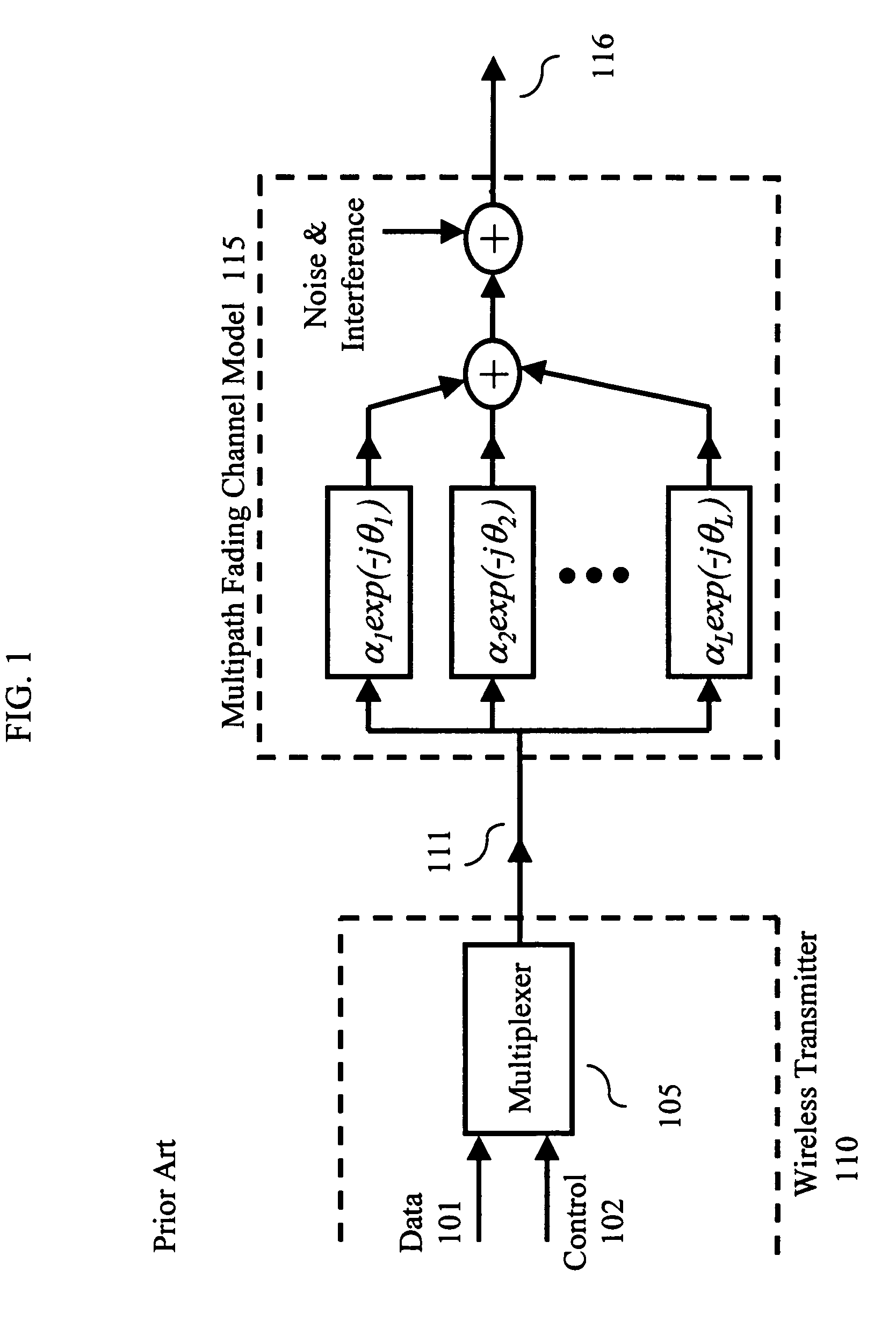
[0013]FIG. 1 illustrates a prior art transmitter and multipath fading model for use in a CDMA-based system such as UMTS. The representations shown in FIG. 1 are well-known and will not be described herein. It is assumed that a BPSK modulation scheme is used, wherein information bits are encoded as +1 or −1. Wireless Transmitter 110 comprises multiplexer 105, which forms, from a data signal 101 (representing a sequence of data symbols) and a control signal 102 (representing a sequence of pilot symbols and other control information, such as a ratio β (defined below)), a PSAM signal 111 for transmission. As known in the art, PSAM signal 111 is subject to fading, noise and interference. These effects are represented by multipath fading model channel 115, which operates on PSAM signal 111 to provide wireless signal 116 for reception by a wireless receiver. (It should be observed that wireless transmitter 110 represents either endpoint of a wireless connection, e.g., a base station or a t...


PUM


Abstract

A universal mobile telecommunications system (UMTS) receiver uses Pilot Symbol Assisted Modulation (PSAM) in demodulating a received Binary Phase Shift Keying (BPSK) signal. The UMTS receiver uses a ratio of the transmitted energy per pilot symbol to the transmitted energy per data symbol as an index into a look-up table to return a value for a scale factor for use in demodulation of the received signal, which provides better performance during periods when the fading distribution is unknown.

Description

FIELD OF THE INVENTION[0001]This invention relates generally to communications and, more particularly, to wireless systems.BACKGROUND OF THE INVENTION[0002]Binary Phase Shift Keying (BPSK) is a popular modulation scheme wherein information bits are encoded as +1 or −1. For channels where the main source of signal distortion is through additive white Gaussian noise (AWGN), the optimal (in terms of minimum error probability) operations to be performed at the receiver are well known. However, in a typical wireless channel, such a transmitted signal undergoes distortion due to fading and path loss in addition to additive noise and interference.[0003]Such fading channels are characterized not only by rapid amplitude and phase variations but also time and / or frequency dispersion. This poses a problem in the demodulation of phase or frequency modulated signals. The fading channel causes rapid changes in the phase thus making it very difficult to infer the phase of the received signal from ...

Claims


Application Information

Patent Timeline
Patent Type & Authority Patents(United States)
IPC IPC(8): H04B15/00H04B1/00H04L25/03
CPCH04L25/03171
Inventor KUMAR, SARATHMONOGIOUDIS, PANTELISREGE, KIRAN MSAMPATH, ASHWIN
Owner LUCENT TECH INC
Why Eureka
Try Eureka