Drained water recovery system and method for operating the same

a technology of drained water and recovery system, which is applied in the direction of process and machine control, instruments, and the nature of treatment water, etc., can solve the problems of reducing productivity, consuming large quantities of water in most wafer cleaning processes, and large portion of the production cost of fabricating integrated circuits

Inactive Publication Date: 2005-10-11
POWERCHIP SEMICON CORP
View PDF7 Cites 2 Cited by
  • Summary
  • Abstract
  • Description
  • Claims
  • Application Information

AI Technical Summary

Benefits of technology

[0007]Accordingly, an object of the present invention is to provide a drained water recovery system and method for operating the sameusing a conductivity meter installed on each processing station to sort out the type of recovered water drained from the particular station before sending to a distribution tank. Hence, contamination in the drained water of any one particular station has no effect on the drained water collection in the process drained water recovery system.

Problems solved by technology

However, most wafer cleaning processes need to consume large quantities of water.
In fact, a large portion of the production cost for fabricating the integrated circuits lies in the purchase of pure water.
However, if the recovery targets at water quantity instead of water quality, the usage of the recovered water may be limited and the ultra-pure water may be contaminated leading to a drop in productivity.
In many cases, the loss in yield that results from the use of contaminated water can hardly warrant the increase in the quantity of recovered water.
Although this method of recovering drained water is able to increase the quantity of recovered water, the quality of the recovered water cannot be improved.
This type of recovery system often leads to some restrictions on the servicing capacity of the recovered water.
Moreover, if a particular type of process drained water is problematic, the entire collection of drained water may have to be discarded.

Method used


Image

  • Drained water recovery system and method for operating the same
  • Drained water recovery system and method for operating the same
  • Drained water recovery system and method for operating the same

Examples


Embodiment Construction

[0021]Reference will now be made in detail to the present preferred embodiments of the invention, examples of which are illustrated in the accompanying drawings. Wherever possible, the same reference numbers are used in the drawings and the description to refer to the same or like parts.

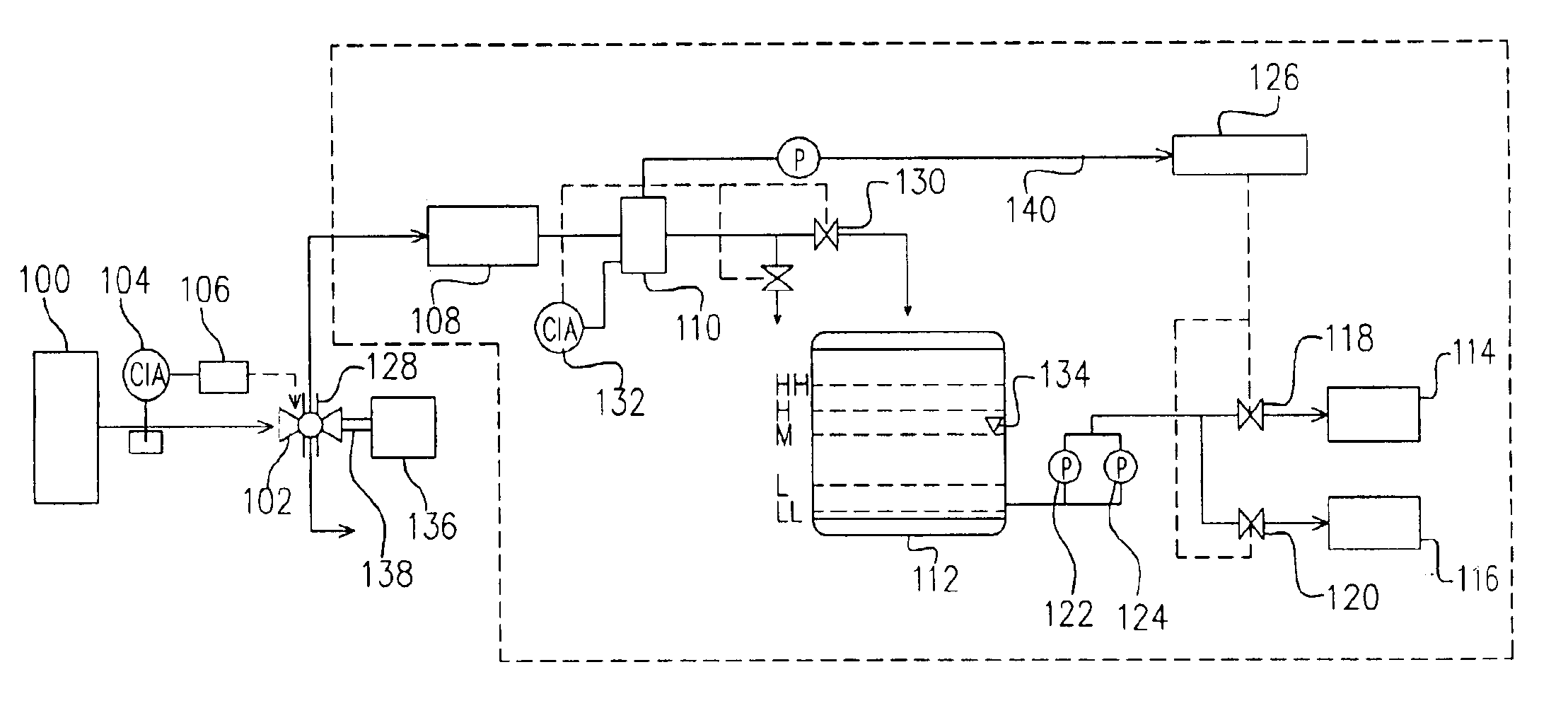
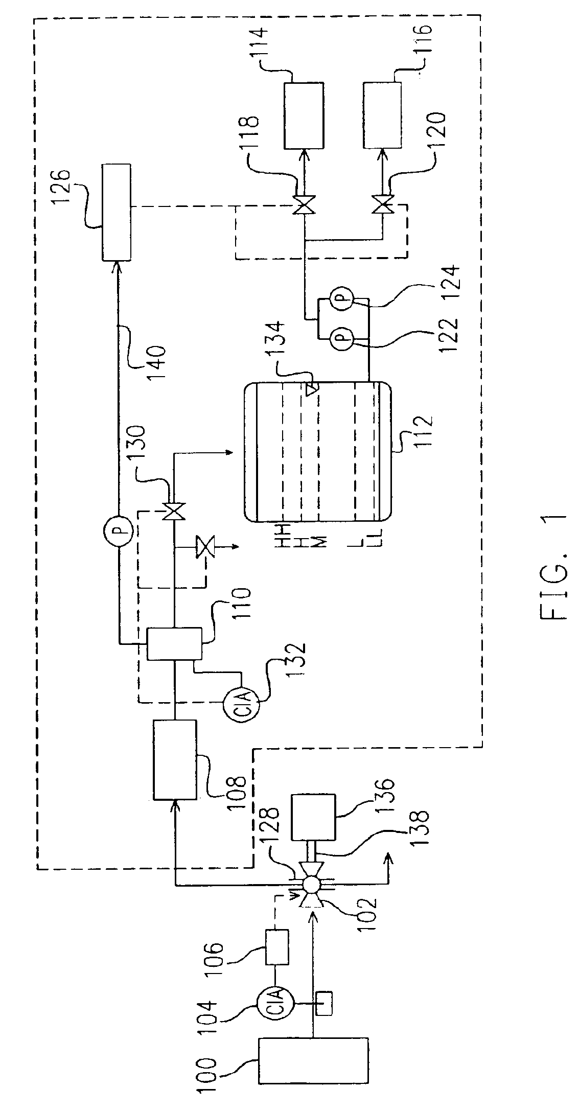
[0022]FIG. 1 is a schematic diagram showing a water recovery and sorting system according to one preferred embodiment of this invention. The drained water recovery system of a process device comprises a processing station 100, a three-way valve 102, a conductivity analyzer 104, a controller 106, a recovery tank 108, a buffer tank 110, an interim tank 112, a first raw water tank 114, a second raw water tank 116, a first valve 118, a second valve 120, a first pump 122, a second pump 124 and a total organic carbon (TOC) analyzer 126. In this invention, a tank is named according to its location. For example, the processed drained water flows out from a processing station to storage tanks inside the facto...


PUM

PropertyMeasurementUnit
heightaaaaaaaaaa
heightaaaaaaaaaa
diameteraaaaaaaaaa

Abstract

A drained water recovery system of a process device and recovering method thereof is provided. The recovering method includes using a conductivity meter to measure the conductivity of the drained water so that the drained water with different degrees of conductivity are channeled to different pipelines. Furthermore, another conductivity meter and a total organic carbon analyzer together with an interim tank liquid level controller sorts out the recovered water. Thereafter, according to the properties of the recovered water, the drained water is re-used to improve recycling efficiency.

Description

BACKGROUND OF INVENTION[0001]1. Field of Invention[0002]The present invention relates to a drained water recovery system and operating method thereof. More particularly, the present invention relates to a drained water recovery system of a process device and an associated recovering method.[0003]2. Description of Related Art[0004]In the fabrication of integrated circuit devices, one of the most frequently performed processes is wafer cleaning. In a wafer cleaning process, organic compounds, metallic impurities and micro-particles are removed from the surface of a wafer. However, most wafer cleaning processes need to consume large quantities of water. In fact, a large portion of the production cost for fabricating the integrated circuits lies in the purchase of pure water. Hence, pure water, cooling water for processing or cooling water for cooling towers is often recycled. If the process of recovering drained water for reuse is properly done, expenses on the necessary water resource...

Claims


Application Information

Patent Timeline
Patent Type & Authority Patents(United States)
IPC IPC(8): C02F1/00
CPCC02F1/008C02F2103/346C02F2209/006C02F2209/05C02F2209/20C02F2209/42Y10T137/0324Y10T137/2509Y10T137/2708
Inventor HUANG, CHENG-CHUNGSUNG, KUN-SEN
Owner POWERCHIP SEMICON CORP
Why Eureka
Try Eureka