
Pneumatic gate valve with an injection-molded valve housing

a technology of injection molding and gate valve, which is applied in the field of pneumatic gate valve, can solve the problems of affecting the operation of the gate valve, the valve housing of a single-part valve is not easy to refinish, and the valve housing of a single-part valve is not easy to clean, so as to reduce the thickness of the material, and enhance the effect of material interconnection

Inactive Publication Date: 2005-10-11
BOSCH REXROTH AG
View PDF14 Cites 2 Cited by
  • Summary
  • Abstract
  • Description
  • Claims
  • Application Information

AI Technical Summary

Benefits of technology

[0009]The present invention resolves prior art problems by using valve bushings which are positioned in place before injection-molding the single-piece valve housing and made of a plastic that has a same melting temperature as the plastic for the valve housing so as to establish a material-interconnecting engagement between the valve bushings and the valve housing, when the valve housing is injection-molded and the plastic material is molded around the valve bushings. Thus, a novel and inventive connection is realized between the valve bushings and the valve housing. The material union eliminates any possibility of gap formation between the valve bushings and the valve housing and is established directly as plastic is molded around the valve bushings, i.e. in a same process step. A sealing material union can be realized by corresponding the melting temperature of the plastic materials for the components being connected, i.e. the valve bushings and the valve housing. As a consequence, a detachment of the valve bushings from inside the valve housing is effectively precluded. Since the material properties of the plastic for the valve bushings and the valve housing are the same, they have also identical thermal expansion coefficients, so that the connection according to the invention remains unaffected, even when exposed to substantial temperature fluctuations.
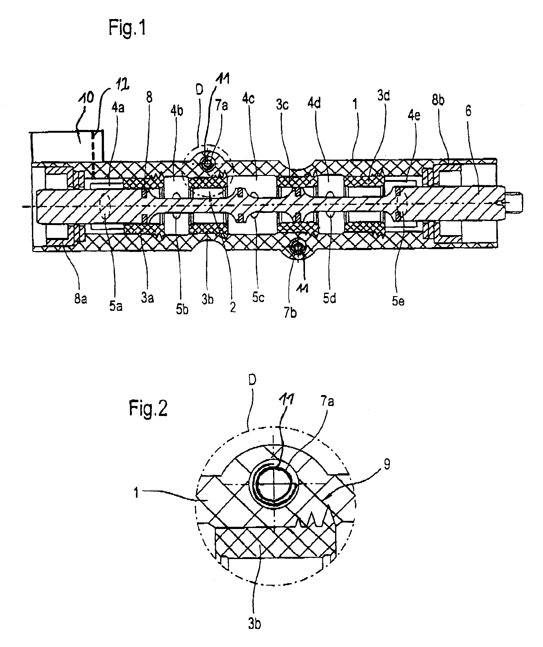
[0010]According to another feature of the present invention, each of the valve bushings may have an outer surface formed with lug-like or spike-like projections of reduced material thickness for enhancing a material interconnection with the plastic material of the valve housing. As a consequence of their reduced material thickness, these projections reach quickly the melting temperature during the injection molding process so as to effectively realize the desired material union.
[0011]Tests have shown that the projections of the valve bushings are preferably tapered at an angle of 25° to 35° so as to ensure a stable form-fitting engagement between the valve bushings and the valve housing in combination with the material union. Construction of the projections of the valve bushings in this particular angle range results in a reliable fusion onto the material surface of the projections as well as in a sufficiently stable configuration, when the valve bushings are exposed to axial stress. The combination of a material union with an additional form-fitting engagement realizes a connection of superior stability.
[0013]A valve housing made of glass-fiber reinforced plastic is especially suitable for threaded connection to a corresponding compressed-air distributing base plate of a valve unit. The glass fiber fraction in plastic inhibits creepage, i.e. a slow plastic deformation when subject to compressive stress. The valve housing has at least one through bore for threadably receiving a corresponding fastening screw for securing the valve housing to the compressed-air distributing base plate, whereby the fastening screw is sufficiently dimensioned to withstand pressure of the valve housing.

Problems solved by technology

Pneumatic gate valves with split valve housing are, however, rather bulky as the contact surface for the seal requires a certain material thickness.
On the other hand, single-part valve housings must be refinished by a complicated material cutting process, after their production through injection molding, especially as far as the interior valve bore for accommodation of the slide member is concerned.
Although this approach may appear to be sound, practice has shown that when a gate valve of this type is used over an extended period or exposed to extreme temperature fluctuations, a clearance between the valve bushings and the valve housing may form that adversely affects the operation of the gate valve.
In extreme situations, the emergence of a gap may lead to an inadvertent flow of pressure fluid between neighboring pressure fluid compartments.
However, as plastic material is molded around the valve bushings as the valve housing is injection-molded, the sealing elements are pushed out of the intended position so that the valve housing cannot be manufactured at reliable reproducibility.

Method used


Image

  • Pneumatic gate valve with an injection-molded valve housing
  • Pneumatic gate valve with an injection-molded valve housing

Examples


Embodiment Construction

[0019]Throughout all the Figures, same or corresponding elements are generally indicated by same reference numerals. These depicted embodiments are to be understood as illustrative of the invention and not as limiting in any way.

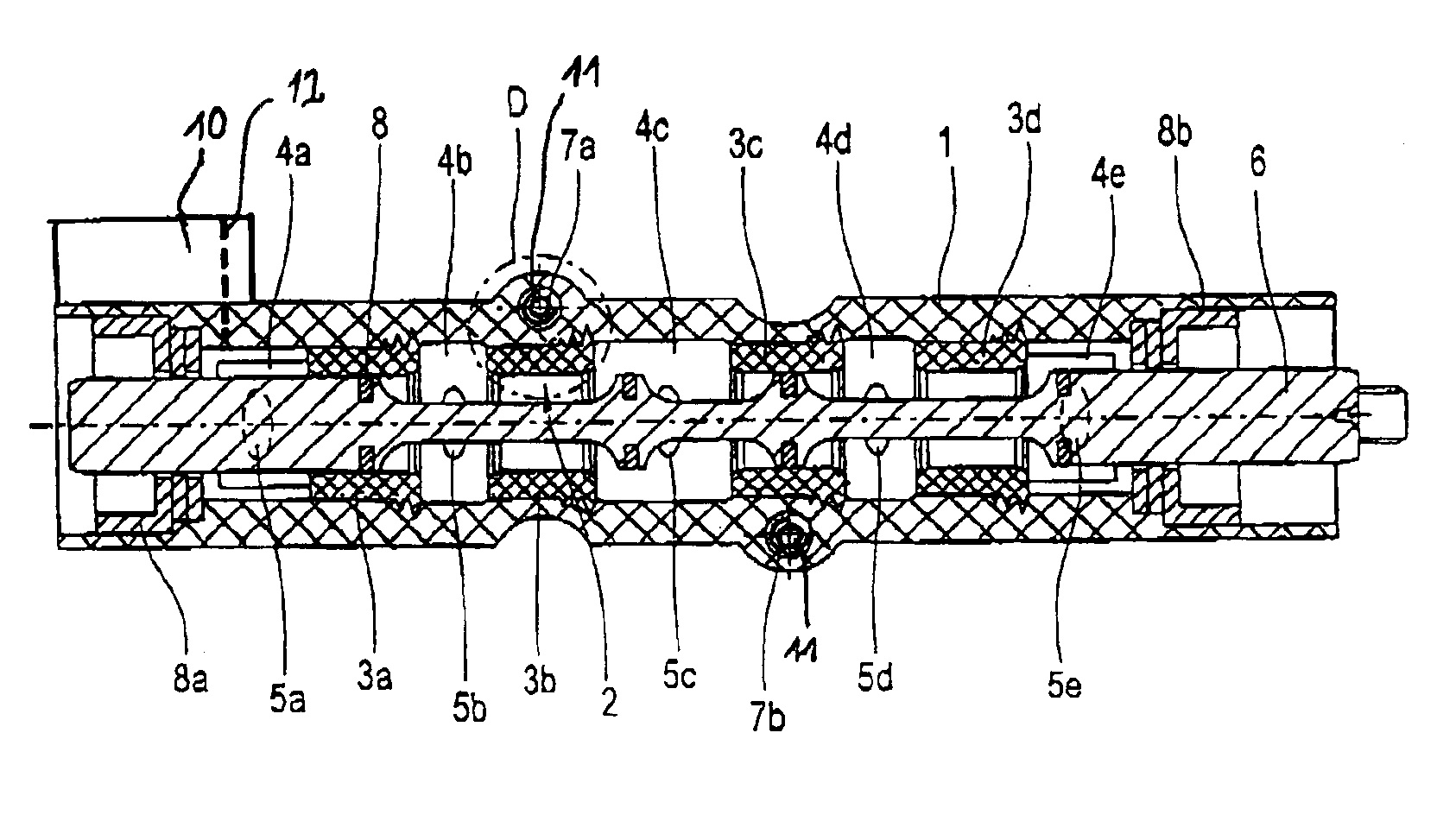
[0020]Turning now to the drawing, and in particular to FIG. 1, there is shown a longitudinal section of a pneumatic gate valve according to the present invention, including a valve housing 1 which is made of injection-molded glass-fiber reinforced polyamide and includes a valve bore 2 in longitudinal direction. The valve bore 2 is formed by a plurality of valve bushings 3a, 3b, 3c, 3d received in the valve housing 1 in axial spaced-apart disposition, thereby defining on both sides of the valve bushings 3a, 3b, 3c, 3d respective pressure fluid compartments 4a, 4b, 4c, 4d, 4e. The pressure fluid compartments 4a, 4b, 4c, 4d, 4e are in fluid communication with respective external ports 5a, 5b, 5c, 5d, 5e, which are shown here partially obscured. In the non-limit...


PUM

PropertyMeasurementUnit
angleaaaaaaaaaa
angleaaaaaaaaaa
pressureaaaaaaaaaa

Abstract

A pneumatic gate valve includes a valve housing made of injection-molded plastic material and having a plurality of external ports. Received in the valve housing are a plurality of valve bushings disposed in axial-spaced relationship as to define a valve bore and a plurality of pressure fluid compartments in fluid communication with the ports. A slide member for regulating a flow of compressed air between the ports is accommodated in the valve bore of the valve housing and displaceable in axial direction. The valve bushings are made of plastic material with a same melting temperature as the plastic material of the valve housing so as to realize a material union between the valve bushings and the valve housing, when plastic material is molded around the valve bushings during injection molding of the valve housing.

Description

CROSS-REFERENCES TO RELATED APPLICATIONS[0001]This application claims the priority of German Patent Application, Serial No. 102 13 258.5, filed Mar. 25, 2002, pursuant to 35 U.S.C. 119(a)-(d), the disclosure of which is incorporated herein by reference.BACKGROUND OF THE INVENTION[0002]The present invention relates, in general, to a pneumatic gate valve, and more particularly to a pneumatic valve gate having a valve housing, which is made of injection-molded plastic material, and a slide member, which is axially movable in a valve bore of the valve housing, for regulating a flow of compressed air between several external ports of the valve housing.[0003]In a pneumatic valve gate of this type, the valve bore is formed by a plurality of valve bushings which are disposed in the interior of the valve housing in axial spaced-apart relationship, thereby defining pressure fluid compartments in fluid communication with the outer ports. The valve housing can be composed of several parts or ma...

Claims


Application Information

Patent Timeline
Patent Type & Authority Patents(United States)
IPC IPC(8): B29C45/14F15B13/00F15B13/04F16K27/04F16K11/07F16K11/065
CPCB29C45/14311F15B13/0402F16K11/0712F16K27/041B29C2045/14319B29K2077/00B29K2105/12B29L2031/7506Y10T137/86686Y10T137/8671
Inventor KULMANN, ERWINBERGMANN, KLAUS
Owner BOSCH REXROTH AG
Learn More