Ferrule for hermetically packaging optical fibers

a technology of ferrules and optical fibers, applied in the field of optical fibers, can solve the problems of affecting the optical communication, damage to the optical fiber cable in the portion to be bonded, and easy damage to the optical fiber cable, etc., and achieve the effect of optical fiber hermetic packaging

Inactive Publication Date: 2005-10-11
SAMSUNG ELECTRONICS CO LTD
View PDF13 Cites 3 Cited by
  • Summary
  • Abstract
  • Description
  • Claims
  • Application Information

AI Technical Summary

Benefits of technology

[0016]Accordingly, the present invention has been made to solve the above-mentioned problems occurring in the prior art and provides further advantages, by providing a ferrule for hermetically packaging optical fibers, from the interior of which it is easy to expel foreign materials, gases, or the like during the solder-injection process to attain an optimal hermetic packaging for optical fibers.

Problems solved by technology

During operation, the optical line is subject to various environments, such as a hot-wet environment, an underwater environment, a toxic environment, or the like, which may have an adverse effect on the optical communication, in particular on a long-distance communication network.
It is easy for the optical-fiber cables to be damaged through a tensile force or an external environment after the installation.
If the passageway of the case 120 is too large, the 120 is not only unsuitable to bond directly with the ribbon-type optical-fiber cable 141 and is also prone to damage the optical-fiber cable in the portion to be bonded.
However, the conventional ferrule has a drawback in that while the solder material is injected into the soldering hole, some foreign materials or gases are not perfectly removed from the hole so that air bubbles remain in the hole after the soldering process which leads to an incomplete seal.
However, there are disadvantages in that air bubbles still remain after the mating between the two bodies as it is impossible to achieve precise mating through the mating process between the upper body 43 and the lower body 41 due to a machining allowance of the components.
However, this ferrule 50 still has a drawback in that while the solder is injected into the soldering hole, foreign materials and gases are not completely removed from the through hole, so that the resulting hermetic packaging cannot satisfy the desired sealing quality.

Method used


Image

  • Ferrule for hermetically packaging optical fibers
  • Ferrule for hermetically packaging optical fibers
  • Ferrule for hermetically packaging optical fibers

Examples


Embodiment Construction

[0029]Hereinafter, preferred embodiments of the present invention will be described in detail with reference to the accompanying drawings. For the purposes of clarity and simplicity, a detailed description of known functions and configurations incorporated herein will be omitted as it may make the subject matter of the present invention unclear.

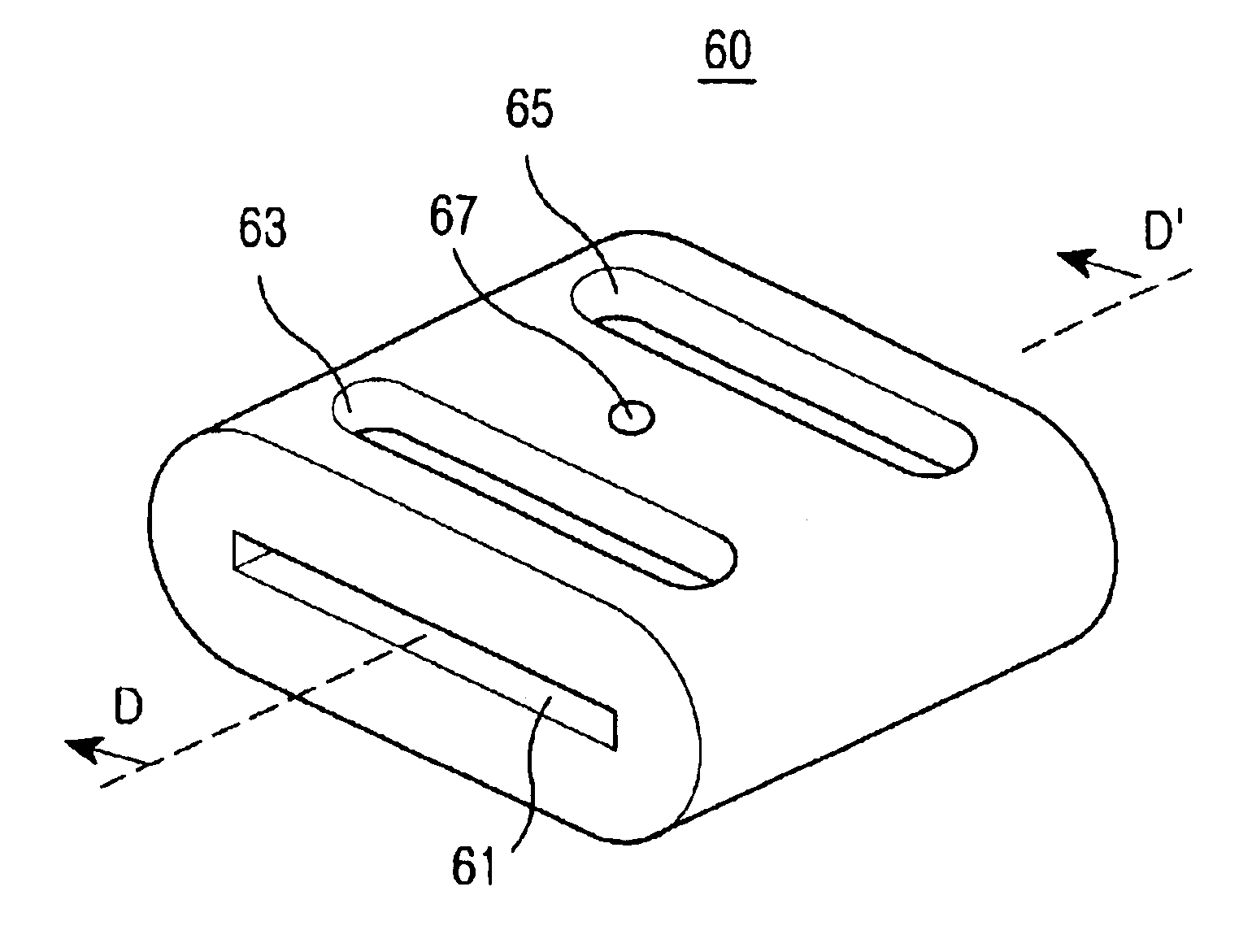
[0030]FIG. 6a is a perspective view of a ferrule 60 for hermetically packaging optical fibers according to the preferred embodiment of the present invention. FIG. 6b is a sectional view of the ferrule 60 shown in FIG. 6a. As shown in FIGS. 6a and 6b, the ferrule 60 includes: a hole 61, which extends in a longitudinal direction and through which a ribbon-type optical-fiber cable passes; a pair of soldering holes 63 and 65 each of which extends from the outer peripheral surface of the ferrule to the hole 61; and, a pinhole 67 disposed between the pair of soldering holes63 and 65 and extending from the outer peripheral surface between the solder...


PUM


Abstract

Disclosed is a ferrule for hermetically packaging optical fibers which includes: an opening provided along a longitudinal direction of the ferrule and having an optical-fiber cable passing there-through; the optical-fiber cable including a plurality of optical-fiber strands; a pair of soldering holes, each extending from a predetermined place on the outer peripheral surface of the ferrule to the through hole; and a pinhole positioned between the soldering holes and extending from a predetermined place on the outer peripheral surface of the ferrule to the through hole.

Description

CLAIM OF PRIORITY[0001]This application claims priority to an application entitled “FERRULE FOR HERMETICALLY PACKAGING OPTICAL FIBERS,” filed in the Korean Industrial Property Office on Aug. 29, 2002 and assigned Serial No. 2002-51361, the contents of which are hereby incorporated by reference.BACKGROUND OF THE INVENTION[0002]1. Field of the Invention[0003]The present invention relates to an optical fiber and, more particularly, to a ferrule device for sealing a connector or other items fitted into the terminal end of the optical-fiber cable in order to hermetically package the optical fibers.[0004]2. Description of the Related Art[0005]In general, an optical fiber serves as an optical-signal-transmission medium used in an optical-communication system. By incorporating a wavelength-division-multiplexing technique in the optical-communication system, the optical system enables superhighway, high-capacity information to be transferred in long-distance communication, thus accelerating ...

Claims


Application Information

Patent Timeline
Patent Type & Authority Patents(United States)
IPC IPC(8): G02B6/42G02B6/38G02B6/36G02B6/30G02B6/00
CPCG02B6/3887G02B6/4248G02B6/30G02B6/3636G02B6/3652G02B6/3855G02B6/4238G02B6/38
Inventor JEONG, BYUNG-GILKWON, OH-DAL
Owner SAMSUNG ELECTRONICS CO LTD
Why Eureka
Try Eureka