

Humidifier for fuel cell
a fuel cell and humidifier technology, applied in the direction of cell components, combustion-air/fuel-air treatment, separation processes, etc., can solve the problems of reducing the output of the fuel cell, and reducing the water recovery rate, so as to prevent or reduce the blocking of the hollow fiber membrane by water
- Summary
- Abstract
- Description
- Claims
- Application Information
AI Technical Summary
Benefits of technology
Problems solved by technology
Method used
Image

Examples
embodiment 1
[0062]A first embodiment of the humidifier for fuel cell according to this invention will be explained with reference to FIGS. 1 to 10.
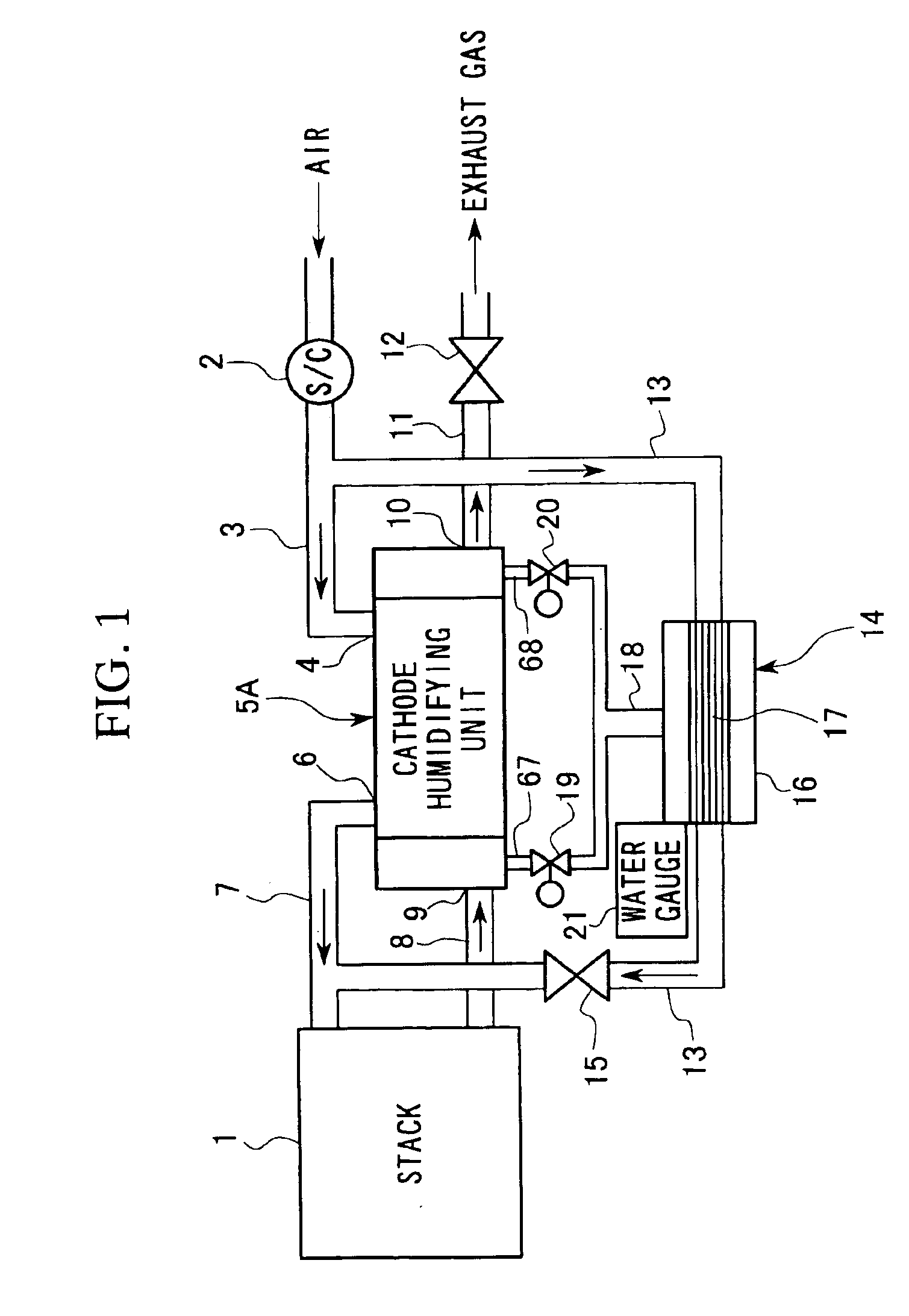
[0063]FIG. 1 is a diagram showing a reactive gas supply system on a cathode side of a fuel cell (hereinafter “stack”) 1 which is mounted in a fuel cell vehicle.
[0064]Oxidizing agent supply gas comprising air is pressurized by a supercharger 2, and supplied via an air supply pipe 3 from a reactive gas entrance 4 to a cathode humidifying unit 5A; the air is humidified as it passes through the cathode humidifying unit 5A. Then, the air is fed out from a reactive gas exit 6 of the cathode humidifying unit 5A along an air supply pipe 7, and via the air supply pipe 7 to the cathode of the stack 1. Oxygen in the air, which has been supplied to the cathode, is used as an oxidizing agent and is thereafter exhausted as exhaust gas (hereinafter “off-gas”) from an off-gas pipe 8 of the stack 1.
[0065]The off-gas contains water, generated at the time of reaction i...
embodiment 2
[0095]A second embodiment of the humidifier for fuel cell according to this invention will be explained based on FIGS. 11 and 12.
[0096]FIG. 11 shows a reactive gas supply system on the cathode side of the stack 1. Parts which are identical to those in the reactive gas supply system already described in the first embodiment are represented by identical reference codes and will not be explained further. Only the points of difference with the first embodiment will be explained below.
[0097]The reactive gas supply system of the second embodiment does not include the drainage holes 67 and 68, the drainage control valves 19 and 20, and the drainage pipe 18 of the cathode humidification unit (water-permeable humidifier) 5A. That is, the cathode humidifying unit 5A of the second embodiment has the same constitution as the conventional humidifier 80 shown in FIG. 17.
[0098]Instead of the above, vapor-liquid separators 30A and 30B for cooling condensation from the off-gas (hereinafter referred ...
embodiment 3
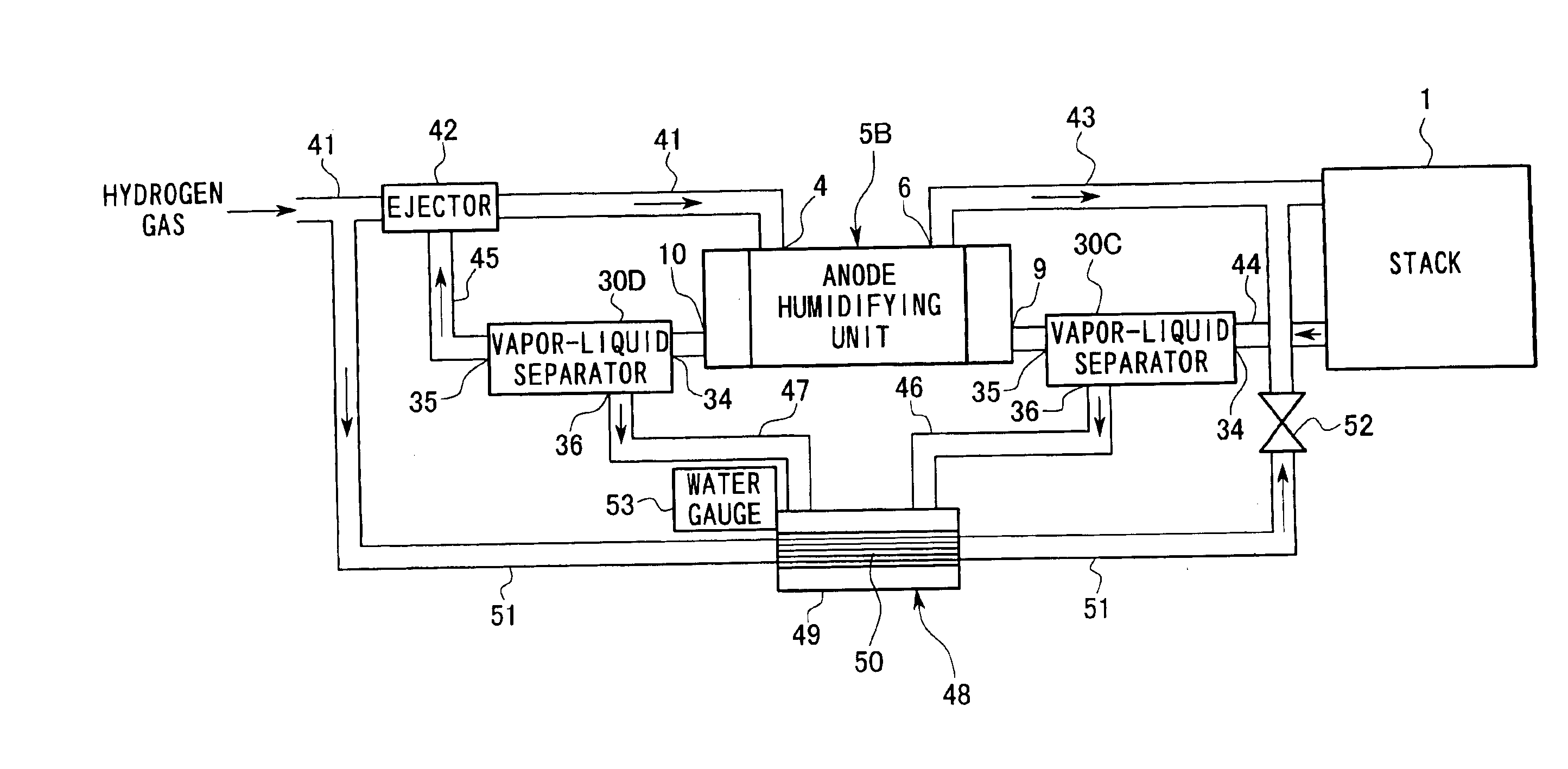
[0105]Subsequently, the humidifier for fuel cell according to a third embodiment of the present invention will be explained with reference to FIG. 13. FIG. 13 shows a reactive gas supply system on the anode side of the stack 1. The anode humidifying unit (water-permeable humidifier) 5B used in this embodiment is the same as the cathode humidifying unit 5A in the second embodiment; same parts are represented by same reference codes and are not explained further.
[0106]Fuel cell supply gas comprises hydrogen gas, and is supplied via a hydrogen supply pipe 41 having an ejector 42 midway therealong from the reactive gas entrance 4 to the anode humidifying unit 5B. After being humidifying while passing through the anode humidifying unit 5B, the hydrogen gas is fed from a reactive gas exit 6 of the anode humidifying unit 5B to a hydrogen supply pipe 43, then along the hydrogen supply pipe 43 to the anode of the stack 1. Part of the hydrogen supplied to the anode is used as fuel, and applie...
PUM
 Abstract
Description
Claims
Application Information