Lead-less surface mount reed relay

a surface mount reed relay and relay technology, applied in relays, dynamo-electric relays, contacts, etc., can solve the problems of inability to meet the requirements of the design process, so as to reduce the profile of the component, greatly improve the frequency response, and reduce the effect of unwanted inductan

Inactive Publication Date: 2005-10-11
MEDER ELECTRONICS
View PDF26 Cites 6 Cited by
  • Summary
  • Abstract
  • Description
  • Claims
  • Application Information

AI Technical Summary

Benefits of technology

[0010]The invention employs a substantially lead-less design that reduces the profile of the component and substantially reduces unwanted inductance. As such, the present invention can be used to switch high frequency signals with greatly improved frequency response. More specifically, the invention enables the ability of the device to switch fast digital pulses at microwave frequencies with shorter or smaller signal paths. Additionally the ability to manufacture the component in modules or arrays allows for inexpensive production of single devices and production of relay array devices with multiple switching nodes.
[0011]I

Problems solved by technology

This transition of the signal leads from plastic dielectric to air creates an undesirable discontinuity of the protective co-axial environment found within the body of the switch itself.
Such discontinuity creates inaccuracy and uncertainty in the impedance of the reed switch device.
This method of discontinuity compensation is not preferred because it complicates a

Method used


Image

  • Lead-less surface mount reed relay
  • Lead-less surface mount reed relay
  • Lead-less surface mount reed relay

Examples


Embodiment Construction

[0027]The novel features characteristic of the present invention are set forth in the appended claims. However, the inventions preferred embodiments, together with further objects and attendant advantages will be best understood by reference to the following detailed description taken in connection with the accompanying drawings, intended to be exemplary only, in which:

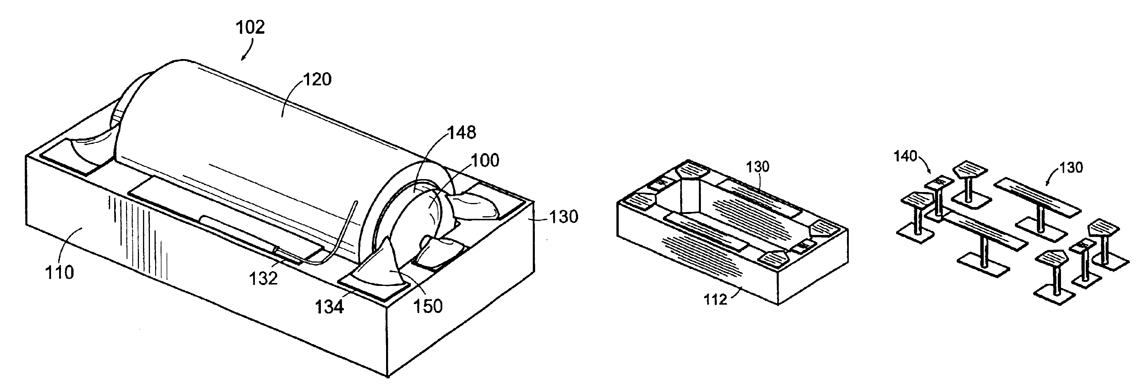
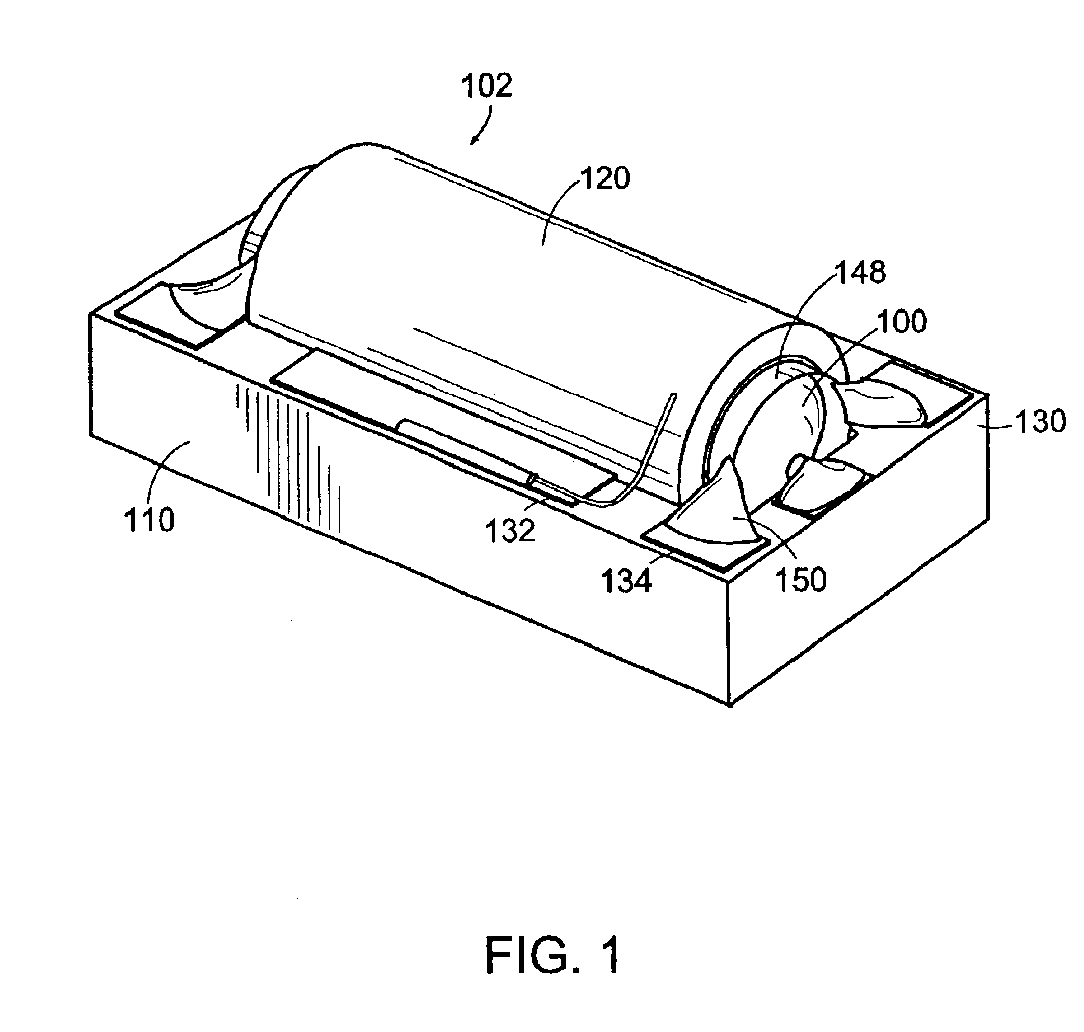
[0028]FIG. 1 shows the present reed switch device, as a single unit. The device as shown does not include the thermoformed over mold matrix, which would cover the internal reed switch component in the finished product. The substrate 110 defines an open aperture capable of receiving the internal component 102. The internal component as shown further comprises a reed switch 100, an electrical shield 148 substantially surrounding the reed switch, and a coil assembly 120 further comprising a coil of electrical wire wound around a coil bobbin, wherein the coil is capable of being electromagnetically energized and thus caus...


PUM


Abstract

A reed relay or reed sensor device that is substantially lead-less and has minimal inductance can be manufactured as an individual unit or as a plurality of units. The reed relay or reed sensor device comprises a substrate that has a plurality contacts on the exterior of the device connected to contacts on the interior of the device capable of maintaining a signal pathway to the internal components of the device. The internal components further comprise a reed switch, an electrical shield, a coil bobbin, and a coil of electrical wire which when energized is capable of effectuating switching in the reed relay.

Description

RELATED APPLICATIONS[0001]This is a continuation of PCT Application Serial Number PCT / US01 / 29056, filed Sep. 18, 2001, which claims the benefit of U.S. Provisional Application Ser. No. 60 / 233,594, filed Sep. 18, 2000, the entirety of all these applications are hereby incorporated herein by reference.FIELD OF THE INVENTION[0002]The present invention relates generally to switching devices. More specifically the present invention relates to a surface mount reed relay or reed sensor that is substantially lead-less, thereby minimizing the signal path and maximizing the frequency response. The resulting inductance and distributed capacitance are significantly lowered, thereby enabling a higher frequency response in the reed switch. The invention also relates to a method of making reed relay components, and arrays of these components.BACKGROUND OF THE INVENTION[0003]Electromagnetic relays have been known in the electronics industry for many years. Such electromagnetic relays include the re...

Claims


Application Information

Patent Timeline
IPC IPC(8): H01H67/24H01H51/00H01H67/00H01H51/28H01H11/00H01H50/10H01H50/00H05K3/34H01H50/04H01H36/00
CPCH01H51/281H01H67/24H01H11/0056H01H50/10H01H2001/5888H05K3/3442
Inventor BEIGEL, JOHNSAMUEL, GUNTHERBOYINGTON, JR., JOHN
Owner MEDER ELECTRONICS
Why Eureka
Try Eureka