Air conditioner with control of compressor

a technology of electric compressor and control system, which is applied in the direction of machines/engines, positive displacement liquid engines, light and heating apparatus, etc., can solve the problems of slow cooling capacity generated in the interior heat exchanger, inability to set the excess value of incremental rotation speed f, and long time to increase the rotation speed of the compressor to the necessary speed

Active Publication Date: 2005-10-18
DENSO CORP
View PDF9 Cites 73 Cited by
  • Summary
  • Abstract
  • Description
  • Claims
  • Application Information

AI Technical Summary

Benefits of technology

[0008]In view of the foregoing problems, it is an object of the present invention to provide an air conditioner in which an actual cooling capacity can be quickly approximated to a target cooling capacity.
[0010]Thus, a capacity of the interior heat exchanger can be more rapidly approximated to a target capacity as compared with a case where the rotation speed of the compressor is determined only by the first target rotation-speed determining means. Therefore, a large cooling capacity can be obtained for a short time period. Accordingly, a temperature in the compartment can be quickly reduced to a comfortable temperature when the air conditioner is started.

Problems solved by technology

Therefore, an excessive value of the incremental rotation speed Δf cannot be set.
Accordingly, it takes a long time to increase the rotation speed of the compressor to a necessary speed.
Thus, the cooling capacity generated in the interior heat exchanger increases slowly and a sufficient cooling capacity may not be obtained, for example, in a quick cooling operation immediately after starting of the compressor.

Method used


Image

  • Air conditioner with control of compressor
  • Air conditioner with control of compressor
  • Air conditioner with control of compressor

Examples


first embodiment

[0031](First Embodiment)

[0032]The first embodiment of the present invention will be now described with reference to FIGS. 1-6.

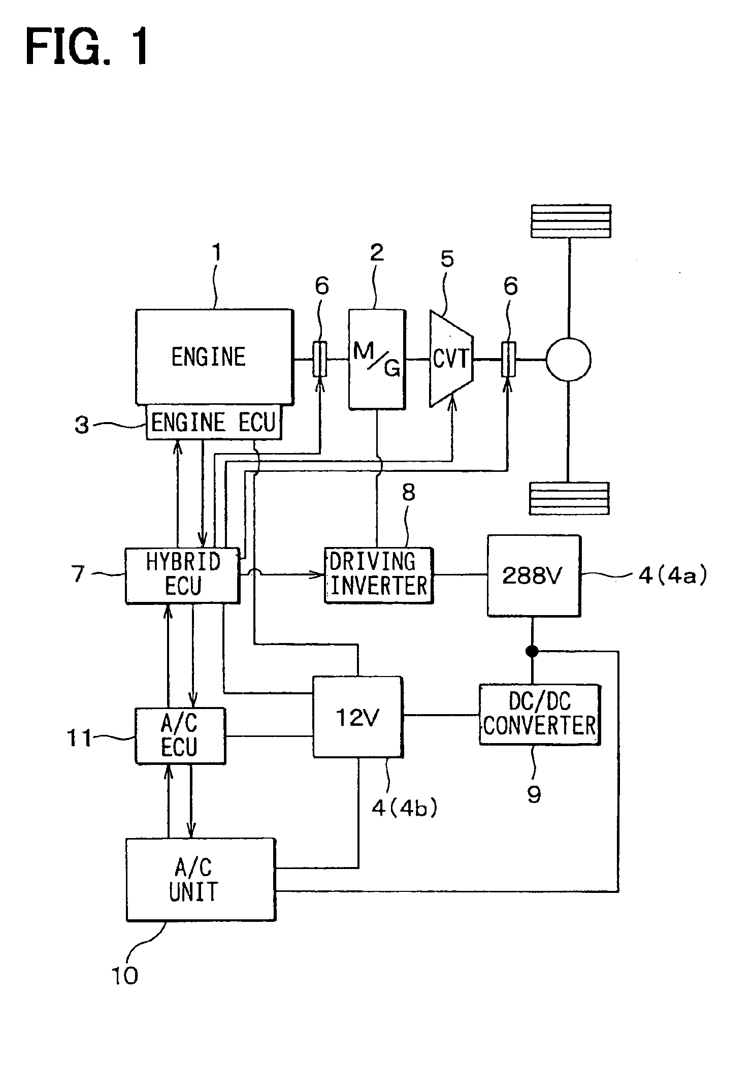
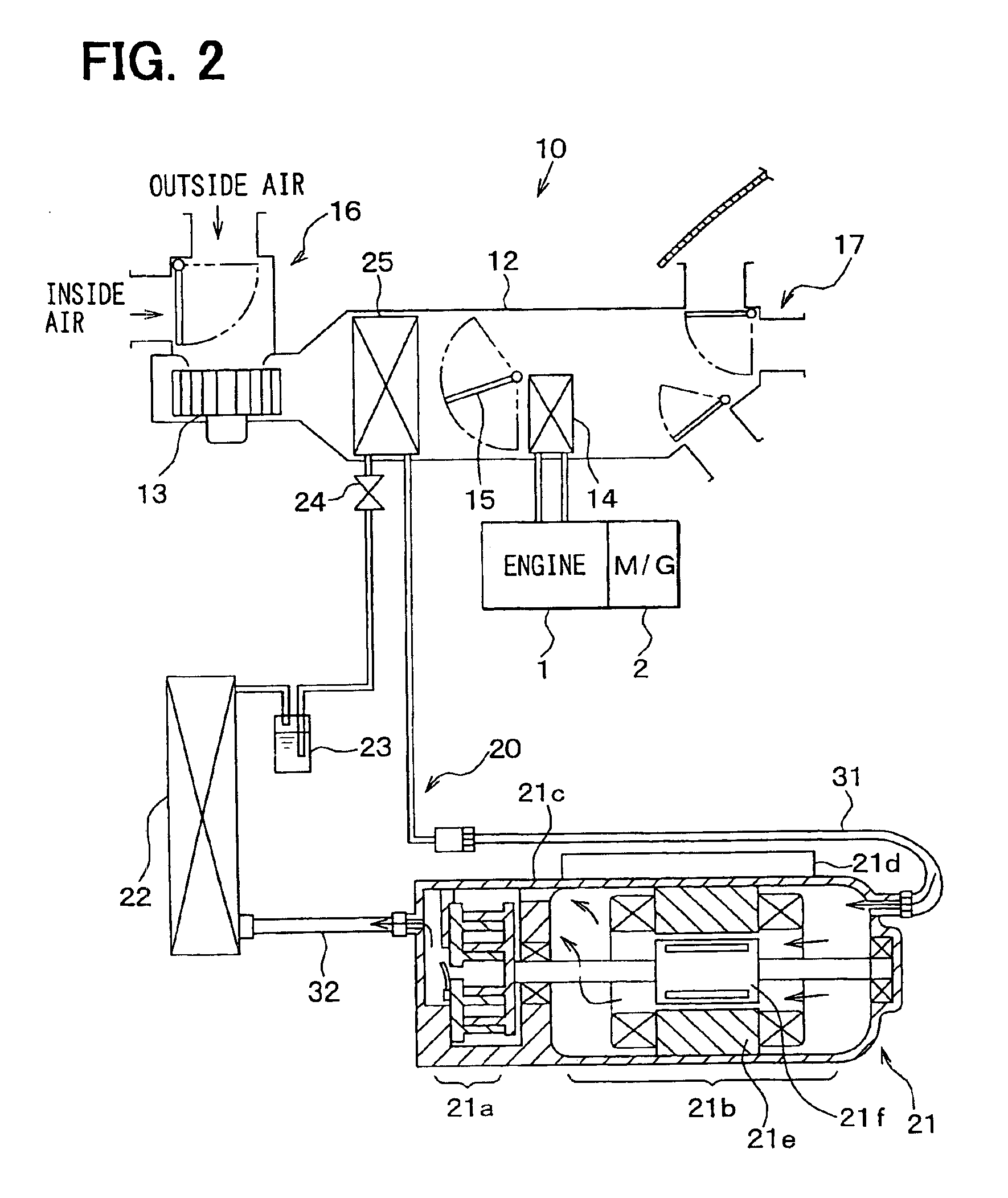
[0033]In the first embodiment, an air conditioner of the present invention is typically used for a hybrid vehicle. As shown in FIG. 1, the hybrid vehicle includes an engine 1, an electric motor generator 2, an engine electronic control unit (ECU) 3, a battery 4 and a hybrid ECU (driving ECU) 7. The engine 1 is an internal combustion engine for generating motive power by exploding and burning liquid fuel such as gasoline. The electric motor generator 2 includes a motor function for an auxiliary driving of the vehicle and a generator function.

[0034]The engine ECU 3 controls an amount of fuel supplied to the engine 1, an ignition time and the like. The battery 4 is a secondary battery which supplies electric power to the electric motor generator 2, the engine ECU 3 and the like. For example, the battery 4 is a nickel-hydrogen storage battery and is composed of a...

second embodiment

[0082](Second Embodiment)

[0083]The second embodiment of the present invention will be now described with reference to FIG. 7.

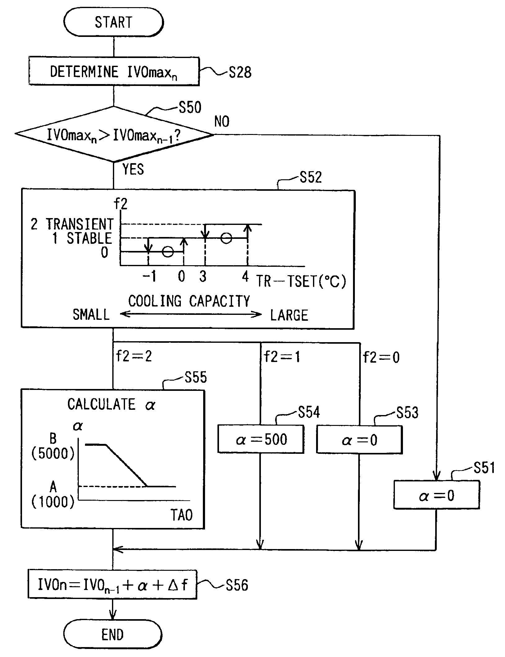
[0084]In the above-described first embodiment, the target compressor rotation speed IVOn is determined at step S23 in FIG. 5, which is different from steps S24-S27, based on the target air temperature TAO when the electric compressor 21 is started. However, in the second embodiment, the target compressor rotation speed IVOn is determined similarly to steps S24-S27 in FIG. 5, even in a case where the electric compressor 21 is started. Specifically, as shown in FIG. 7, the difference En and the Edot are calculated at step S24a and step S25a, similarly to steps S24 and S25. Then, at step S26a, the incremental rotation speed Δf is calculated based on the difference En between the target evaporator air temperature TEO and the evaporator air temperature TE. Then, at step S26b, the incremental rotation speed Δf is corrected to Δf′ by multiplying a correction coeffici...

third embodiment

[0085](Third Embodiment)

[0086]The third embodiment of the present invention will be now described with reference to FIG. 8.

[0087]In the above-described first embodiment, the target compressor rotation speed IVOn is determined at step S23 in FIG. 5, which is different from steps S24-S27, based on the target air temperature TAO when the electric compressor 21 is started. However, in the third embodiment, as shown in FIG. 8, when the electric compressor 21 is started at step S22, the difference En between the target evaporator air temperature TEO and the evaporator air temperature TE, and the difference change rate Edot are calculated at steps S24a and S25a. Then, at step S26c, the target incremental rotation speed Δf(START) at the difference En and the difference change rate Edot is calculated based on a predetermined start membership function and a start rule stored in the ROM. Here, the predetermined start membership function and the start rule are different from those at step S26. ...


PUM


Abstract

In an air conditioner, a target compressor rotation speed is determined based on a target air temperature, which represents an air conditioning load, when an electric compressor is started from a stop state. Thus, an evaporator air temperature can be approximated to a target evaporator air temperature, more quickly as compared with a control method where an incremental rotation speed is added to a present rotation speed of the electric compressor, that is, 0 rpm. Accordingly, a large cooling capacity can be obtained for a short time period. Thus, an air temperature in a compartment can be quickly reduced to a comfortable temperature, when the air conditioner is started, for example.

Description

CROSS REFERENCE TO RELATED APPLICATION[0001]This application is based on Japanese Patent Applications No. 2003-111719 filed on Apr. 16, 2003 and No. 2003-285179 filed on Aug. 1, 2003, the disclosures of which are incorporated herein by reference.BACKGROUND OF THE INVENTION[0002]1. Field of the Invention[0003]The present invention relates to an air conditioner. More particularly, the present invention relates to a control system for controlling an electric compressor of the air conditioner.[0004]2. Description of Related Art[0005]In an air conditioner disclosed in JP-A-2001-26214, a control target rotation speed fn of a compressor is determined as follows. That is, an actual cooling capacity TE (e.g., air temperature immediately after an evaporator) generated in an interior heat exchanger is detected, a target cooling capacity TEO of the interior heat exchanger is determined, and a difference ΔTE between the TE and the TEO is calculated. Then, an incremental rotation speed Δf with re...

Claims


Application Information

Patent Timeline
Patent Type & Authority Patents(United States)
IPC IPC(8): F25B49/02B60H1/32F04B49/06
CPCB60H1/322F25B49/025B60H2001/3261B60H2001/3266B60H2001/327B60H2001/3292F25B2500/19F25B2500/26F25B2600/0253F25B2700/2104F25B2700/2106F25B2700/21172F25B2700/21173
Inventor HOMAN, TOSHINOBUOOMURA, MITSUYOYOSHIDA, MAKOTO
Owner DENSO CORP
Why Eureka
Try Eureka