Slider

a technology of sliding and sliding plate, which is applied in the field of sliding plate, can solve the problems of easy wear of the pattern printed on the board or the pattern on the sticker stamped on the board, and users don't feel comfortable when physically touching the plate,

Inactive Publication Date: 2005-10-18
AGIT GLOBAL IP HLDG LLC
View PDF10 Cites 38 Cited by
  • Summary
  • Abstract
  • Description
  • Claims
  • Application Information

AI Technical Summary

Benefits of technology

[0007]It is therefore primary objective of the present invention to provide a slider that can resist corrosion of moisture, dirt and ultraviolet of sunlight at all sides.
[0008]Another object of the invention is to provide a slider that can prevent the pattern on the slider from wear and tear.

Problems solved by technology

Although hardened plastic has a nature of wear resisting, users don't feel comfortable when physically contact with the board.
The traditional slider is heavy, so it's not convenient for users especially children to carry it.
Besides, the pattern printed on the board or the pattern on a sticker stamped on the board is easily worn out since it directly contacts human body, air and sunlight.
It is known that the ultraviolet will result the damage of the expended polyethylene.
The air-cells on the surfaces of the out layer and the out strips are fragile when frictionized.
Once the air-cells in or on the out layer are broken, water will retained in the dents formed by the broken air-cells and therefore reduce the life and workability of the board.
Furthermore, the pattern on the slider can only be printed on the out layer and the out strips.
The wear and tear of a slider is significant if used frequently.
Users of sliders also don't like the pattern to be worn out quickly.

Method used


Image

  • Slider
  • Slider
  • Slider

Examples


first embodiment

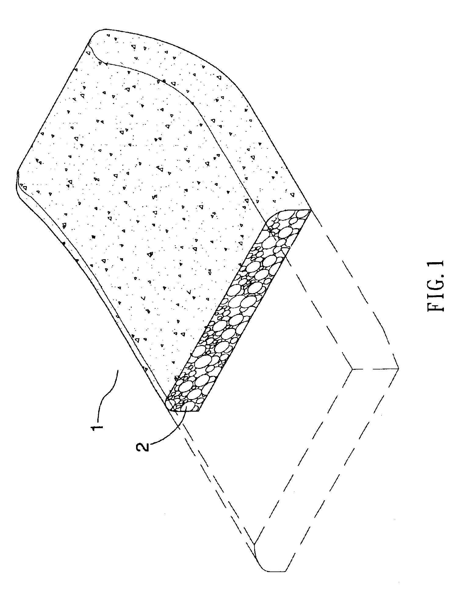
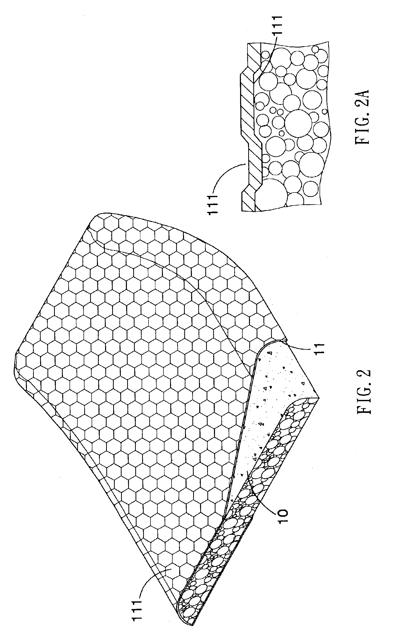
[0023]FIG. 2 illustrates the present invention. The embodiment contains a polyethylene foaming board 10 and a plastic film 11 encapsulating and bonding with the polyethylene foaming board 10. The plastic film 11 has plural small concaves 111 on both sides. The polyethylene foaming board 10 is united with the concaves 111 at the inner side of the plastic film 11. Thereby the bonding surface between the plastic film 11 and the polyethylene foaming board 10 is increased. Accordingly the bonding strength is greatly increased. The plastic film 11 can prevent the ultraviolet rays of the sunshine from directly projecting on the polyethylene foaming board 10 and moisture from directly contacting the polyethylene foaming board 10. The concaves 111 at the outer side of the plastic film 11 can provide stronger traction between human body and the outer side of the plastic film, so users of the slider can hold on the slider firmly.

second embodiment

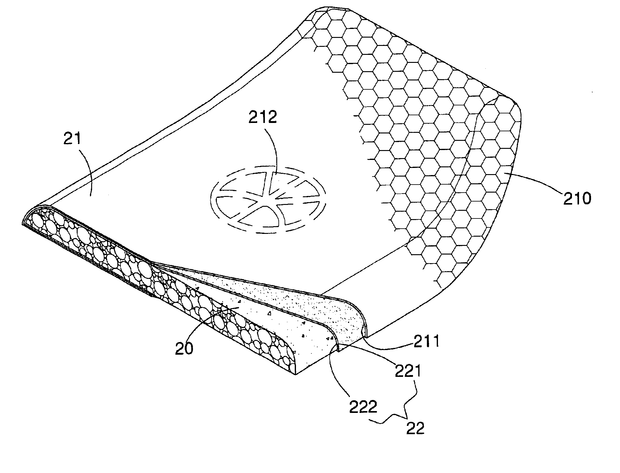
[0024]With reference to FIG. 3, the present invention contains a polyethylene foaming board 20, an outer film 21 and an inner film 22. The outer film 21 contains an inner surface 211 having a pattern 212 thereon. The outer film 21 is pervious to light, so the pattern 212 can be seen through. The inner film 22 contains an outer surface 221 and an inner surface 222. The outer surface 221 of the first inner film 22 is bonded with the inner surface 211 of the outer film 21 including the pattern 212. The inner surface 222 of the first inner film 22 is bonded with the polyethylene foaming board 20. The outer film 21 together with the inner film 22 have plural concaves 210 on the outer surface of the outer film 21 and on the inner surface 222 of the inner film 22. The polyethylene foaming board 20 is united with the concaves 210 at the inner surface 222 of the inner film 22. Thereby the pattern 212 is protected by the outer film 21 from wear and tear. The cells of the polyethylene foaming ...

third embodiment

[0026]With reference to FIG. 4, the present invention contains a polyethylene foaming board 30, a first polyethylene foaming skin 31, a first plastic film 33, a second polyethylene foaming skin 32 and a second plastic film 34.

[0027]The polyethylene foaming board 30 has a top surface 301, a bottom surface 303 and edge surfaces 302. The first polyethylene foaming skin 31 contains an inner surface 312 bonded with the top surface 301 and the edge surfaces 302 of the polyethylene foaming board 30, and an outer surface 311. The first polyethylene foaming skin 31 has a foaming rate less than a foaming rate of the polyethylene foaming board 30. The first plastic film 33 is bonded with the outer surface 311 of the first polyethylene foaming skin 31. The second polyethylene foaming skin 32 contains an inner surface 321 bonded with the bottom surface 303 of the polyethylene foaming board 30, and an outer surface 322. The second polyethylene foaming skin 32 has a foaming rate less than the foam...


PUM

PropertyMeasurementUnit
thicknessesaaaaaaaaaa
thicknessaaaaaaaaaa

Abstract

A slider that can resist corrosion of moisture, dirt and ultraviolet of sunlight and prevent the pattern therein from wear and tear. The slider also provides a smooth touching feeling to users. The slider mainly containing: a polyethylene foaming board, a first polyethylene foaming skin, a first plastic film, a second polyethylene foaming skin and a second plastic film. The polyethylene foaming board having a top surface, a bottom surface and edge surfaces. The first polyethylene foaming skin contains an inner surface and an outer surface. The inner surface of the first polyethylene foaming skin is bonded with the top surface and the edge surfaces of the polyethylene foaming board. The first polyethylene foaming skin has a foaming rate less than a foaming rate of the polyethylene foaming board. The first plastic film is bonded with the outer surface of the first polyethylene foaming skin. The second polyethylene foaming skin contains an inner surface and an outer surface. The inner surface of the second polyethylene foaming skin is bonded with the bottom surface of the polyethylene foaming board. The second polyethylene foaming skin has a foaming rate less than the foaming rate of the polyethylene foaming board. The second plastic film is bonded with the outer surface of the second polyethylene foaming skin.

Description

[0001]The present invention is a continuation-in-part application of the U.S. Ser. No. 10 / 040,404, application filed on Jan. 9, 2002, now abandoned.TECHNICAL FIELD[0002]This invention relates generally to a slider, in particular, to provide a slider having at least one protective layer protecting the foaming material of the slider from corrosion of moisture, dirt and ultraviolet of sunlight and the pattern on the slider from wear and tear.[0003]The slider can be used as a bodyboard, a snowboard, a snow sled, a grass sliding board, sand sliding board or the like.BACKGROUND OF THE INVENTION[0004]A traditional slider used as a snowboard contains a board and two handles installed at two sides. The slider has pattern thereon. The traditional board is made of hardened plastic because hardened plastic is wear resistant. Although hardened plastic has a nature of wear resisting, users don't feel comfortable when physically contact with the board. The traditional slider is heavy, so it's not ...

Claims


Application Information

Patent Timeline
Patent Type & Authority Patents(United States)
IPC IPC(8): A63C5/00A63C5/03B29C70/00B29C70/86B32B5/18B63B35/73B62B15/00B32B37/15B32B38/06B63B35/79
CPCA63C5/03B29C70/865B32B5/18B62B15/00B63B35/7909B29L2031/52B32B37/153B32B38/06B32B38/145B32B2305/022B62B2501/065B63B2035/7903B63B2231/50B63B32/57B32B27/065
Inventor YEH, TZONG IN
Owner AGIT GLOBAL IP HLDG LLC
Why Eureka
Try Eureka