PVD target constructions comprising projections

a technology of projection and target construction, which is applied in the direction of electrolysis components, vacuum evaporation coatings, coatings, etc., can solve the problems of affecting the desired properties of the film, the formation of very large particles is not often reduced to the desired level, and the formation of very large particles

Inactive Publication Date: 2005-10-18
HONEYWELL INT INC
View PDF7 Cites 18 Cited by
  • Summary
  • Abstract
  • Description
  • Claims
  • Application Information

AI Technical Summary

Problems solved by technology

Problems can occur in deposition processes if particles are formed, in that the particles can fall into a deposited film and disrupt desired properties of the film.
Although some of the textured surfaces have been found to reduce particle formation, the particle formation is frequently not reduced to a desired level.
In some instances, the texturing on a sidewall surface of a target can ultimately lead to formation of very large particles.
The films can fall onto a substrate during a PVD process to cause a defect in a layer deposited during the PVD process.
This problem is frequently encountered with textures which have been formed through machine scrolling and / or knurling.
Another problem is that the formation of a textured surface can itself introduce contaminants.
Some of the particles from for the blasting can be imbedded in the target during the blasting process, remain with the target as it is inserted in a PVD chamber, and then fall from the target during a sputtering process to become problematic contaminants during the sputtering.

Method used


Image

  • PVD target constructions comprising projections
  • PVD target constructions comprising projections
  • PVD target constructions comprising projections

Examples


Embodiment Construction

[0030]This disclosure of the invention is submitted in furtherance of the constitutional purposes of the U.S. Patent Laws “to promote the progress of science and useful arts” (Article 1, Section 8).

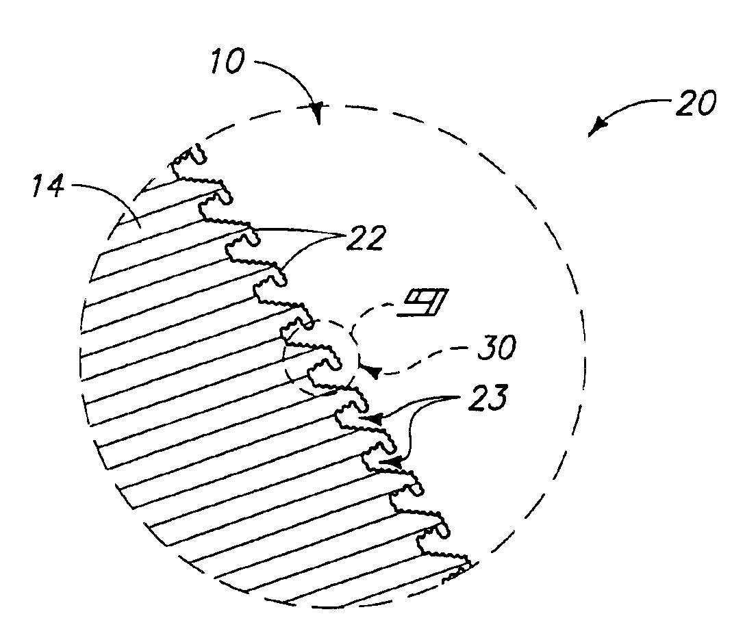
[0031]The invention encompasses new textures which can be formed on one or more surfaces of a PVD target or target / backing plate assembly, and utilized for trapping sputtered materials which redeposit on the target or assembly. In a particular aspect, curved projections (such as, for example, a bent scroll pattern) are formed on non-sputtered surfaces of a target or target / backing plate assembly to form particle trapping areas. The non-sputtered surfaces can include sidewall surfaces, flange surfaces and / or non-sputtered surfaces along a sputtering face. The projections can be exposed to particles to roughen surfaces of the projections. The projections can be considered to form a macro-scale roughness of a trapping area, and the roughened surfaces of the projections can be considered to f...


PUM

PropertyMeasurementUnit
heightaaaaaaaaaa
distanceaaaaaaaaaa
repeat distanceaaaaaaaaaa

Abstract

The invention includes PVD targets having non-sputtered regions (such as, for example, sidewalls), and particle-trapping features formed along the non-sputtered regions. In particular aspects, the particle-trapping features can comprise a pattern of bent projections forming receptacles, and can comprise microstructures on the bent projections. The targets can be part of target / backing plate constructions, or can be monolithic. The invention also includes methods of forming particle-trapping features along sidewalls of a sputtering target or along sidewalls of a target / backing plate construction. The features can be formed by initially forming a pattern of projections along a sidewall. The projections can be bent and subsequently exposed to particles to form microstructures on the bent projections.

Description

RELATED PATENT DATA[0001]This patent claims priority to U.S. Provisional Patent Application 60 / 396,543, which was filed Jul. 16, 2002.TECHNICAL FIELD[0002]The invention pertains to methods of forming particle traps along non-sputtered regions of a physical vapor deposition (PVD) target construction, and pertains to PVD target constructions having projections along at least one non-sputtered region.BACKGROUND OF THE INVENTION[0003]Deposition methods are utilized for forming films of material across substrate surfaces. Deposition methods can be utilized in, for example, semiconductor fabrication processes to form layers ultimately utilized in fabrication of integrated circuitry structures and devices. An exemplary deposition method is physical vapor deposition (PVD), which includes sputtering processes.[0004]A physical vapor deposition operation is described with reference to a sputtering apparatus 110 in FIG. 1. Apparatus 110 is an example of an ion metal plasma (IMP) apparatus, and ...

Claims


Application Information

Patent Timeline
Patent Type & Authority Patents(United States)
IPC IPC(8): C23C14/34
CPCC23C14/3407H01J37/3491H01J37/3435H01J37/3414C23C14/081C23C14/0635
Inventor KIM, JAEYEON
Owner HONEYWELL INT INC
Why Eureka
Try Eureka